
Hybrid pyrolysis system and method

a hybrid pyrolysis and pyrolysis technology, applied in the direction of indirect heat exchangers, lighting and heating apparatus, coke ovens in horizontal chambers, etc., can solve the problems of inability to achieve pyrolysis, and low quality of the result of such decomposition process, etc., to achieve efficient pyrolysis of organic materials

Active Publication Date: 2022-05-31
BIOFORCE TECH CORP
View PDF6 Cites 0 Cited by
  • Summary
  • Abstract
  • Description
  • Claims
  • Application Information

AI Technical Summary

Benefits of technology

This patent describes a method and system for efficiently pyrolyzing organic material. The method involves heating the organic material in a reactor to a high temperature and then separating it into two main products, syngas and carbonized material. The syngas is then burnt in a combustion chamber to produce exhaust gas. This exhaust gas is then used to heat thermal fluids, which are sent back to the reactor to facilitate the process. The system includes a bin for organic material, a reactor, pipes for separating the pyrolyzed organic material, a combustion chamber, and thermal fluid exchangers. Overall, this technology allows for a more efficient and effective way to handle organic material and produce energy.

Problems solved by technology

In the past, several attempts have been made in order to find a way to thermally decompose organic materials at elevated temperatures in an inert atmosphere that could be energy efficient, but until now without success.
Moreover, the quality of the result of such decomposition process (which is commonly called pyrolysis), has always been very low and therefore of scarce economic value.
Currently, there are three industrial pyrolysis systems and methods that are used, and all of them have multiple disadvantages that make them inefficient.
The real downside of this system is the energy consumption.
In order to make this process economically viable, it would be necessary to produce more energy than is required to perform the pyrolysis, but with an electrical pyrolysis system it is actually not possible.
The downside also of this system is once again the energy consumption.
The energy recovered from the Syngas combustion can used for other purposes but it a non-economically viable amount of energy if compared to the quantity of natural gas or propane that is required to keep the pyrolysis process in place.
Moreover, since the energy comes from an external source (like natural gas), it cannot be recovered in any way or substituted efficiently in order to hear and keep the temperature of the reactor.
No electrical resistors are used in this kind of pyrolysis system and method, and no energy is produced from the combustion of the Syngas.
The huge downside of this system is the difficulty to maintain a specific temperature in the rector: the temperature can be too high or too low.
Counterbalancing the temperature through the use of external energy is expensive and strongly diminishes the efficiency of the process.
While in principle advantageous, this system and method is actually very expensive.
The instability and scarce predictability of the temperatures is such, unless adequately balanced, that the carbonized material resulting from the pyrolysis is of very low quality, unless a lot of energy is consumed to keep a balanced temperature in the reactor.
The above described three methods and systems are the most common and commercially exploitable ways to perform a pyrolysis, but they all have serious problems that impair their efficiency and so their commercial viability.

Method used


Image

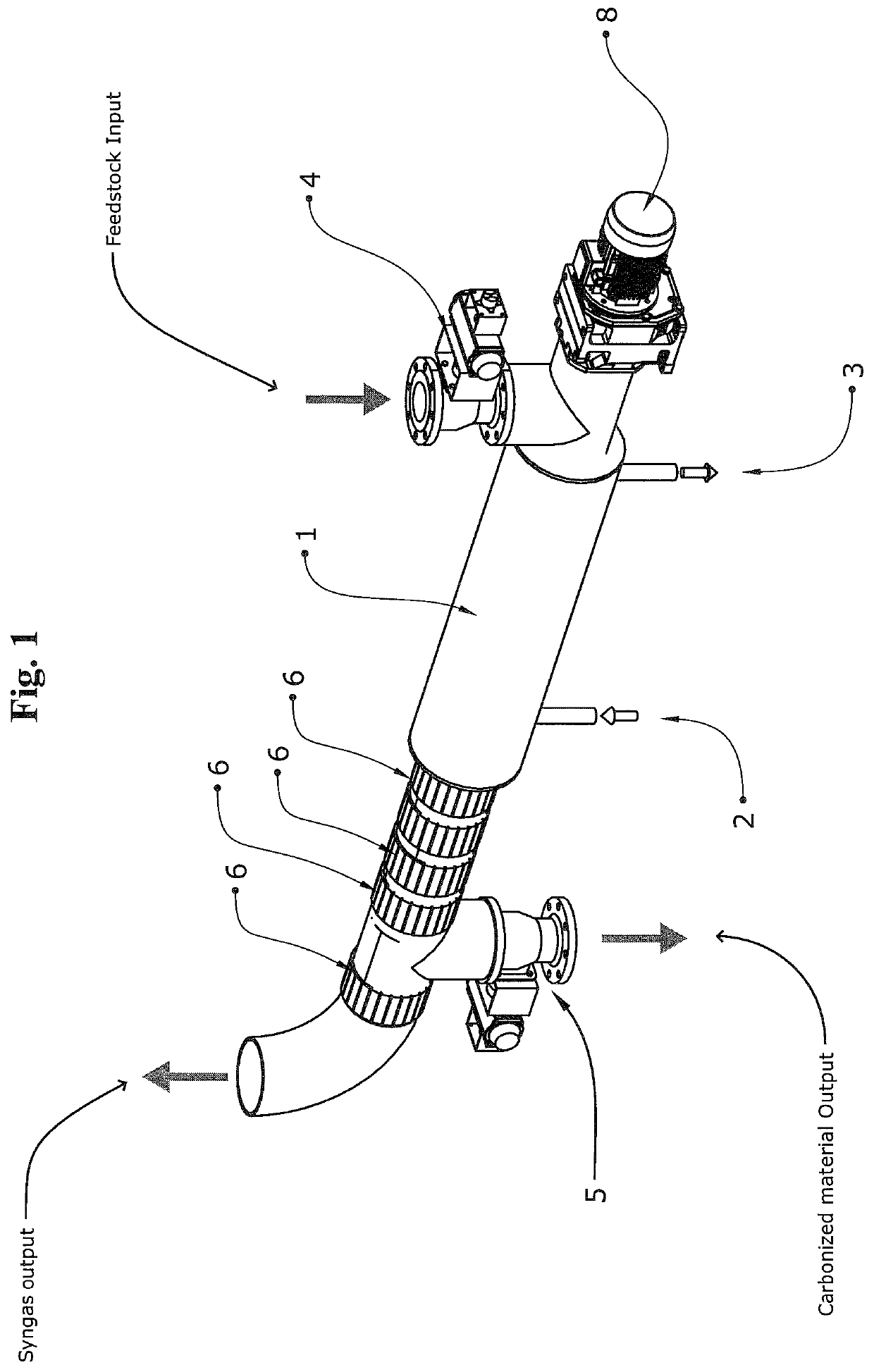
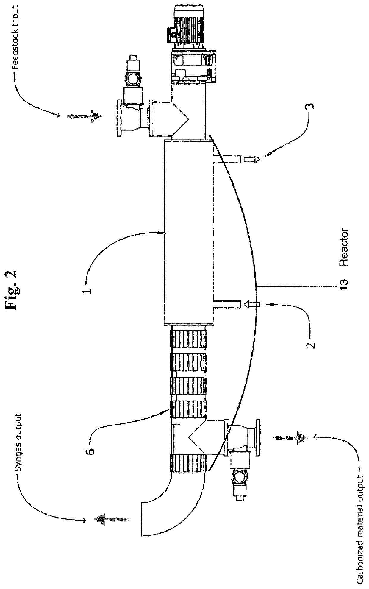
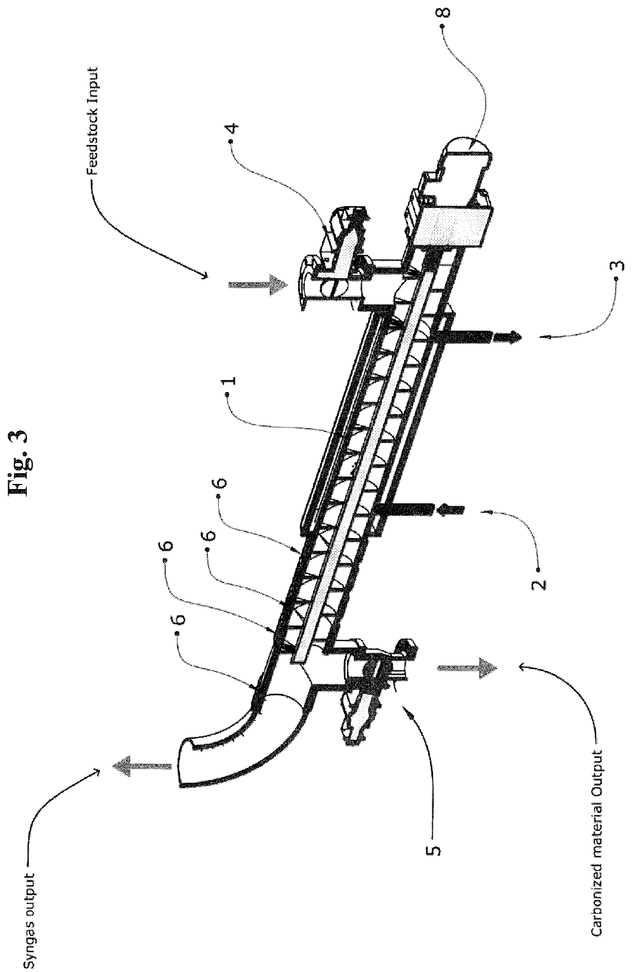
  • Hybrid pyrolysis system and method
  • Hybrid pyrolysis system and method
  • Hybrid pyrolysis system and method

Examples


Embodiment Construction

[0019]As already mentioned in the Background, systems and methods for performing the pyrolysis of organic materials have been invented a long time ago, and there are actually many ways to perform pyrolysis.

[0020]Three of the most common and commercially frequent ways in which pyrolysis of organic material is carried out have been referenced to in the Background, but all of them have one or more disadvantageous properties which make them non-economically viable, due to excess of energy which is required to perform the pyrolysis in a way which allows to obtain a resulting carbonized material that can be reused and it is therefore of good quality.

[0021]The present disclosure aims at solving the aforementioned inefficiency and quality problems.

[0022]Embodiments of the disclosure include a method to efficiently carry out the pyrolysis of organic material. In one of the embodiments, such method may be performed through the injection of organic material in a container, also called reactor ...


PUM

PropertyMeasurementUnit
temperatureaaaaaaaaaa
temperaturesaaaaaaaaaa

Abstract

A system and method for performing pyrolysis comprises a reactor through which organic material is conveyed from an upstream end toward a downstream end and within which said pyrolysis will occur; a combustion chamber fluidically connected to the downstream end of the reactor; an output pipe fluidically connected to the downstream end of the reactor; a capsule surrounding a first part of the reactor and into an internal portion of which heated thermal fluids are disposed for heating the first part of said reactor; and a plurality of electrical resistors disposed around a second part of the reactor for heating the second part of the reactor; whereby, as a result of the pyrolysis occurring within the reactor, the syngas is conducted toward the combustion chamber while the carbonized material is conducted outwardly from the reactor through the output pipe.

Description

FIELD OF THE INVENTION[0001]Various embodiments of the present invention generally relate to a new and energy-positive method of thermal decomposition of organic materials at elevated temperatures in an inert atmosphere.BACKGROUND OF THE INVENTION[0002]Pyrolysis is the thermal decomposition of organic materials at elevated temperatures (usually between 450° C. and 900° C.) in an inert atmosphere (absence of oxygen). It involves the change of chemical composition and is irreversible. The pyrolysis produces two main results: a gas (also called “Syngas”) and a carbonized material. In the past, several attempts have been made in order to find a way to thermally decompose organic materials at elevated temperatures in an inert atmosphere that could be energy efficient, but until now without success. Moreover, the quality of the result of such decomposition process (which is commonly called pyrolysis), has always been very low and therefore of scarce economic value.[0003]Currently, there a...

Claims


Application Information

Patent Timeline
Patent Type & Authority Patents(United States)
IPC IPC(8): C10B47/18C10B47/44C10B19/00C10B1/06C10B5/10C10B7/10F28D7/16H02K7/18
CPCC10B19/00C10B1/06C10B5/10C10B7/10C10B47/44F28D7/16H02K7/1815B09C1/065C10B53/02Y02E50/10B09B3/40
Inventor PRESEZZI, DARIOVILLA, VALENTINOMOSCIARELLO, MARCOPESSINA, STEFANOBONFANTI, MATTIA
Owner BIOFORCE TECH CORP
Learn More