A biomass pyrolysis liquefaction polygeneration system

A biomass pyrolysis and biomass technology, which is applied in the preparation of liquid hydrocarbon mixtures, the selection of absorbent solid gas purification, special forms of dry distillation, etc., can solve the problems of low coke quality, complex pyrolysis bio-oil components, thermal Solve problems such as low calorific value of gas, achieve the effects of reducing pretreatment costs, enhancing heat radiation capabilities, and saving energy consumption

Active Publication Date: 2019-10-25
HUAZHONG UNIV OF SCI & TECH
View PDF1 Cites 0 Cited by
  • Summary
  • Abstract
  • Description
  • Claims
  • Application Information

AI Technical Summary

Problems solved by technology

[0004] Aiming at the above deficiencies or improvement needs of the prior art, the present invention proposes a biomass pyrolysis liquefaction polygeneration system, which through the key components biomass pretreatment subsystem, pyrolysis subsystem, pyrolysis volatile fractionation condensation Subsystem, pyrolysis gas purification subsystem and fuel gas adsorption proton extraction system specific structure and specific assembly method research and design, can realize the comprehensive and efficient utilization of biomass, and at the same time obtain high-quality activated carbon, graded liquid oil and clean Gas products solve the problems of low quality coke obtained by the current biomass pyrolysis polygeneration technology, complex components of pyrolysis bio-oil, and low calorific value of pyrolysis gas. It has high processing efficiency, high heat utilization rate, and convenient operation. Strong applicability and other advantages

Method used


Image

  • A biomass pyrolysis liquefaction polygeneration system
  • A biomass pyrolysis liquefaction polygeneration system
  • A biomass pyrolysis liquefaction polygeneration system

Examples


Embodiment Construction

[0062] In order to make the object, technical solution and advantages of the present invention clearer, the present invention will be further described in detail below in conjunction with the accompanying drawings and embodiments. It should be understood that the specific embodiments described here are only used to explain the present invention, not to limit the present invention. In addition, the technical features involved in the various embodiments of the present invention described below can be combined with each other as long as they do not constitute a conflict with each other.

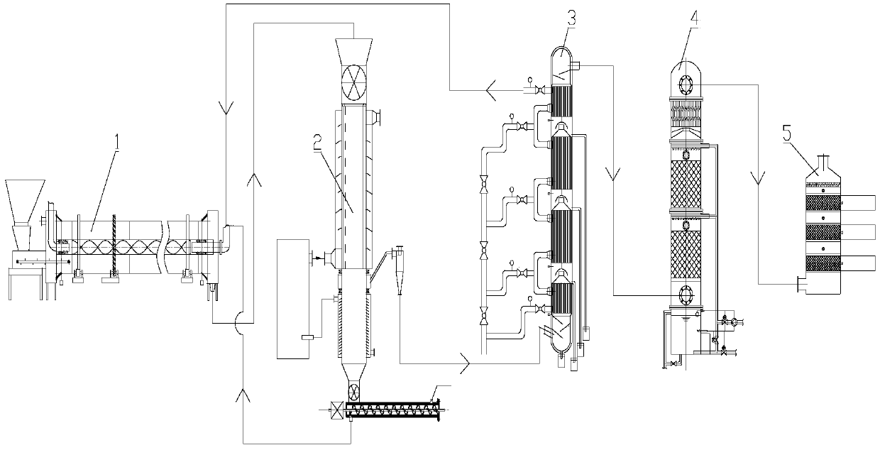
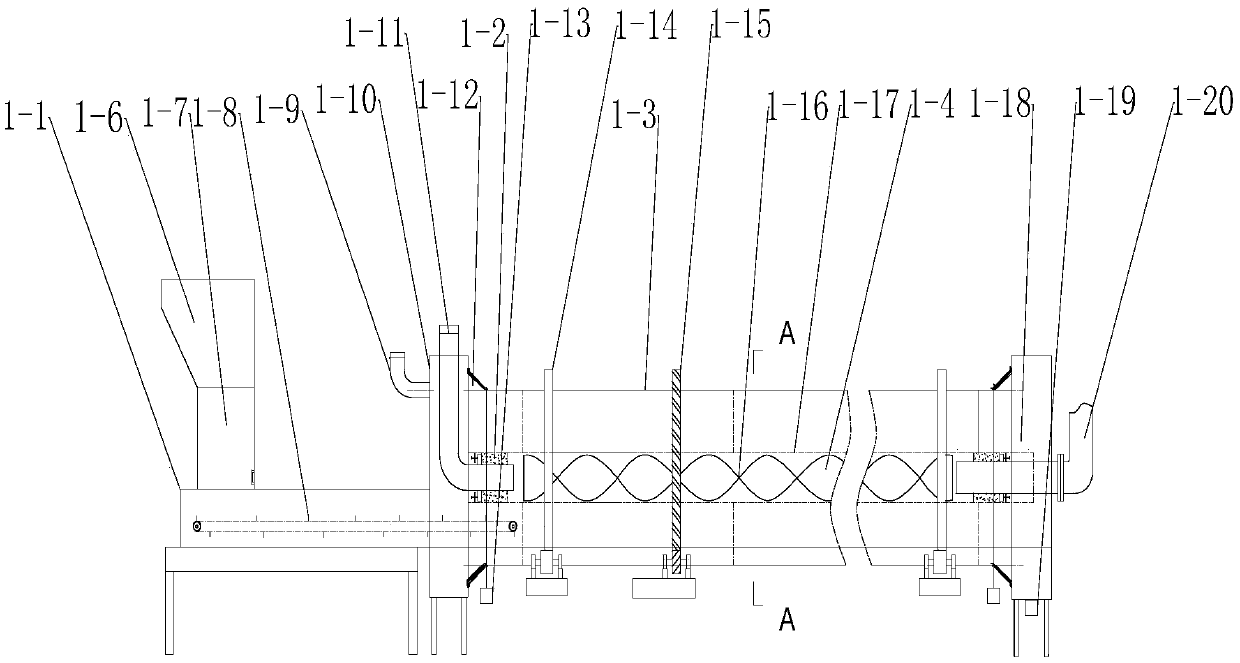
[0063] Such as figure 1 As shown, a biomass pyrolysis liquefaction multi-generation system provided by the embodiment of the present invention is used to perform pyrolysis reaction on biomass to co-produce activated carbon, graded liquid oil and clean gas products, including successively connected biomass Substance Pretreatment Subsystem 1, Pyrolysis Subsystem 2, Pyrolysis Volatile Condensation...


PUM


Abstract

The invention belongs to the technical field of biomass treatment, and specifically discloses a biomass pyrolysis liquefaction polygeneration system. The system comprises a biomass pre-treatment sub-system, a pyrolysis sub-system, a multi-stage condensation sub-system, a pyrolysis gas purification sub-system, and a gas adsorption upgrading sub-system that are connected in sequence, wherein the biomass pre-treatment sub-system is used for pre-treating a biomass raw material so as to obtain a biomass semi-coke product, the pyrolysis sub-system is used for pyrolyzing the biomass semi-coke productso as to obtain pyrolysis volatiles and coke, the multi-stage condensation sub-system is used for condensing the pyrolysis volatiles in multiple stages so as to obtain various biological oils and pyrolysis gases, the pyrolysis gas purification sub-system is used for spraying and condensing the pyrolysis gas so as to condense and dissolve acetic acid steam in the pyrolysis gas to obtain wood vinegar and coarse gas, and the gas adsorption upgrading sub-system is used for adsorbing the coarse gas to remove impurities, so as to obtain a clean gas product rich in methane. The biomass pyrolysis liquefaction polygeneration system has the advantages of high treatment efficiency, high heat use ratio, convenience in operation, high applicability and the like.

Description

technical field [0001] The invention belongs to the technical field of biomass treatment, and more specifically relates to a biomass pyrolysis liquefaction polygeneration system. Background technique [0002] Pyrolysis is a way to efficiently convert biomass. Using pyrolysis technology, biomass can be quickly converted into three valuable products: charcoal, gas and oil. At present, the technical development of biomass pyrolysis focuses more on the optimal utilization of a single product, but does not pay enough attention to other products, and its economy is often difficult to guarantee. The development of carbon, gas and oil polygeneration technology based on biomass pyrolysis to produce a variety of high value-added products can effectively realize the economic maximization of the entire conversion process, and is an important direction for the comprehensive utilization of biomass resources. [0003] Patent CN201210241955.7 discloses a biomass pyrolysis carbon gas-oil po...

Claims


Application Information

Patent Timeline
Patent Type & Authority Patents(China)
IPC IPC(8): C10B53/00C10G1/00C10K1/32
CPCC10B53/00C10G1/00C10K1/32
Inventor 陈汉平陈伟陈应泉杨海平王贤华邵敬爱张雄杨晴张世红
Owner HUAZHONG UNIV OF SCI & TECH
Why Eureka
Try Eureka