Compact star tracker with photonic crystal pointing

a star tracker and photonic crystal technology, applied in direction/deviation determining electromagnetic systems, instruments, optical elements, etc., can solve the problems of difficult correction of refractive errors and high size and weight requirements of gimbaled systems

Active Publication Date: 2022-06-07
THE UNITED STATES OF AMERICA AS REPRESETNED BY THE SEC OF THE AIR FORCE
View PDF38 Cites 0 Cited by
  • Summary
  • Abstract
  • Description
  • Claims
  • Application Information

AI Technical Summary

Problems solved by technology

A gimbal mechanism provides a wide field of view; however, the size and weight requirements of the gimbaled system are quite high.
The Risley prism approach introduces refractive errors that are difficult to correct for in systems that detect an extended spectrum.

Method used


Image

  • Compact star tracker with photonic crystal pointing
  • Compact star tracker with photonic crystal pointing
  • Compact star tracker with photonic crystal pointing

Examples


Embodiment Construction

[0015]The present innovation provides a celestial tracking device (referred to in this document generically as a star tracker), particularly as the hardware used for celestial body sightings. Rotating photonic crystals are provided for beam pointing and a flat mirror is used to fold the optical path, making the star tracker more compact. In particular, the photonic crystal pointing requires specially designed spatially variant photonic crystals (SVPCs).

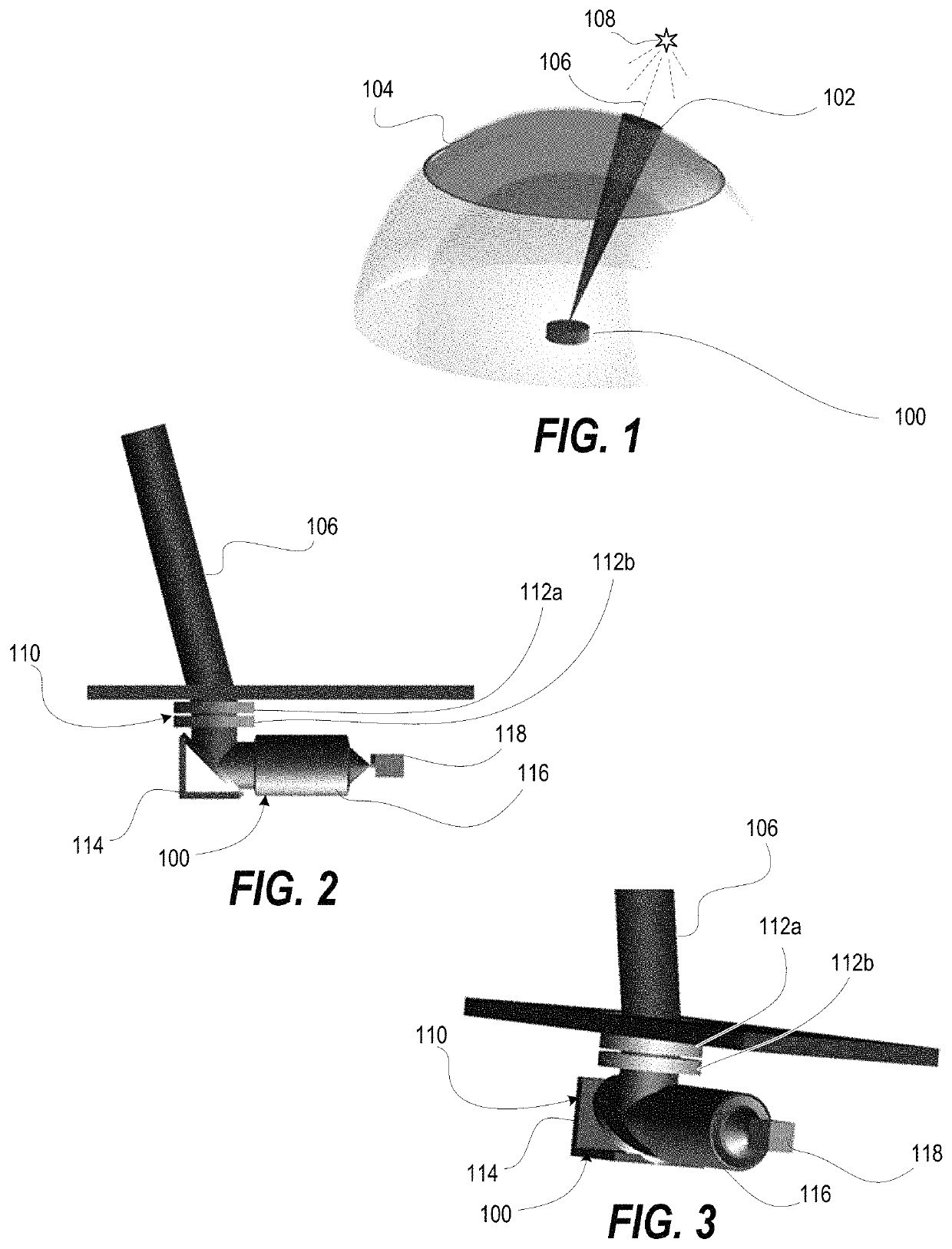
[0016]FIG. 1 depicts a celestial tracking device (“star tracker”) 100 that is steerable to a field of view (FOV) 102 within a total field of regard (FOR) 104 to track a light beam 106 from a celestial object 108. FIGS. 2-3 depict a side view and an isometric view of the star tracker 100 having a steering system 110 that enables detection of the light beam 106 that is off-axis. The steering system 110 is composed of a pair of rotating photonic crystal elements 112a, 112b designed for optical deflection. The steering system 110 is analo...


PUM

PropertyMeasurementUnit
angleaaaaaaaaaa
angleaaaaaaaaaa
field of viewaaaaaaaaaa

Abstract

A star tracker includes imaging optics comprising a folding mirror, a lens, and a detector. The folding mirror bends light received from an optical axis through the lens that focuses the bent light onto the detector. The star tracker includes a steering mechanism that steers light from an adjustable field of view (FOV) to the optical axis of the imaging optics. The steering mechanism includes: (i) a first photonic crystal element comprising beam pointing spatially variant photonic crystals (SVPCs); (ii) a second photonic crystal element comprising beam pointing SVPCs that is positioned adjacent and axially aligned with the first photonic crystal element; and (iii) a housing that receives the first and second photonic crystal elements for independent rotation.

Description

CROSS-REFERENCE TO RELATED APPLICATIONS[0001]This application claims the benefit of priority under 35 U.S.C. § 119(e) to U.S. Provisional Application Ser. No. 62 / 880,991 entitled “ Compact Star Tracker with Photonic Crystal Pointing”, [Docket AFD-1886P] filed 31 Jul. 2019, the contents of which are incorporated herein by reference in their entirety.ORIGIN OF THE INVENTION[0002]The invention described herein was made by employees of the United States Government and may be manufactured and used by or for the Government of the United States of America for governmental purposes without the payment of any royalties thereon or therefore.BACKGROUND1. Technical Field[0003]The present disclosure generally relates to optical devices and more particular to celestial optical tracking devices.2. Description of the Related Art[0004]Traditional star trackers employ detectors fixed to refractive lenses or reflective telescopes which are then pointed around a field of regard (FOR) using a gimbal, fl...

Claims


Application Information

Patent Timeline
Patent Type & Authority Patents(United States)
IPC IPC(8): G02B1/00G02B6/122G02B23/10G01S3/786
CPCG02B1/005G01S3/7867G02B6/1225G02B23/105G02B26/0808G02B26/0891
Inventor LENTZ, JOSHUABRINK, KEVIN
Owner THE UNITED STATES OF AMERICA AS REPRESETNED BY THE SEC OF THE AIR FORCE
Why Eureka
Try Eureka