Ultra thin and compact dual polarized microstrip patch antenna array with 3-dimensional (3D) feeding network

a patch antenna array, multi-dimensional technology, applied in the direction of polarised antenna unit combinations, individually energised antenna arrays, resonant antennas, etc., can solve the problems of reducing the gain of the array antenna, limiting the bandwidth, and increasing surface wave and spurious feed radiation

Active Publication Date: 2022-08-09
NETCOMM WIRELESS
View PDF6 Cites 0 Cited by
  • Summary
  • Abstract
  • Description
  • Claims
  • Application Information

AI Technical Summary

Benefits of technology

[0009]The inventive concept arises from a recognition that it is beneficial to reduce the width of the microstrip line, with an arbitrary characteristic impedance matching network at the same layer of patch antenna element, in a 3-dimensional (3D) feeding network using air as a dielectric, and to reduce the side lobes level and improve the gain of the array antenna. Also, reducing the width of microstrip line for a multiple patch element antenna array through a 3D microstrip line feeding network using air as a dielectric allows each patch antenna element and the upper layer of microstrip line in dual polarisation to electrically fit and physically fit into a compact array antenna footprint without deteriorating the isolation between two polarisations.
[0011]The 3D microstrip line feeding network may further comprise at least one vertical matching impedance bridge connecting the upper layer to the lower layer, the at least one vertical matching impedance bridge is configured to operate as a transformer of the upper layer of the 3D microstrip line feeding network for reducing side lobe level (SLL).
[0027]The 3D microstrip line feeding network comprises an upper layer. The 3D microstrip line feeding network also comprises a lower layer. The 3D microstrip line feeding network also comprises at least one vertical matching impedance bridge connecting the upper layer to the lower layer. The at least one vertical matching impedance bridge is configured to operate as a transformer of the upper layer of 3D microstrip line feeding network for reducing side lobe level (SLL).
[0031]The multiple patch antenna element array antenna provides a compact that increases the array antenna gain by reducing the side lobes levels by using a 3D microstrip line feeding network using air as a dielectric. The present invention provides an ultra thin profile, compact and inexpensive patch antenna array.

Problems solved by technology

The disadvantage of this feeding method for a microstrip antenna array is that increasing the RF PCB substrate thickness to increase the bandwidth causes surface wave and spurious feed radiation to increase.
This limits the bandwidth and reduces the array antenna gain because of the increase of unwanted side lobes levels.
Sometimes, the size of the patch element is too large and the strip line is too wide to prevent use of the microstrip antenna array, especially when the patch elements and the strip lines are at the same height and also if constrained by the maximum geometric profile or footprint allowable for the antenna array.

Method used


Image

  • Ultra thin and compact dual polarized microstrip patch antenna array with 3-dimensional (3D) feeding network
  • Ultra thin and compact dual polarized microstrip patch antenna array with 3-dimensional (3D) feeding network
  • Ultra thin and compact dual polarized microstrip patch antenna array with 3-dimensional (3D) feeding network

Examples


Embodiment Construction

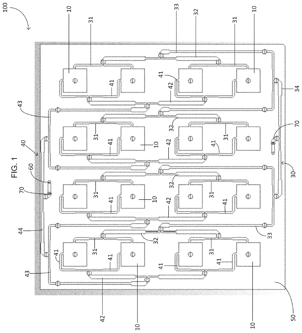
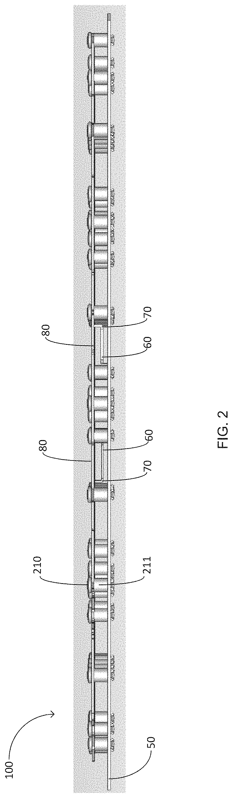
[0061]A preferred dual polarized directional array according to the present invention is illustrated in FIGS. 1 and 2 and shown generally at reference numeral 100.

[0062]The dual polarized directional array antenna 100 comprises a plurality of antenna elements 10 and a 3D microstrip line feeding network 30, 40 using air as a dielectric.

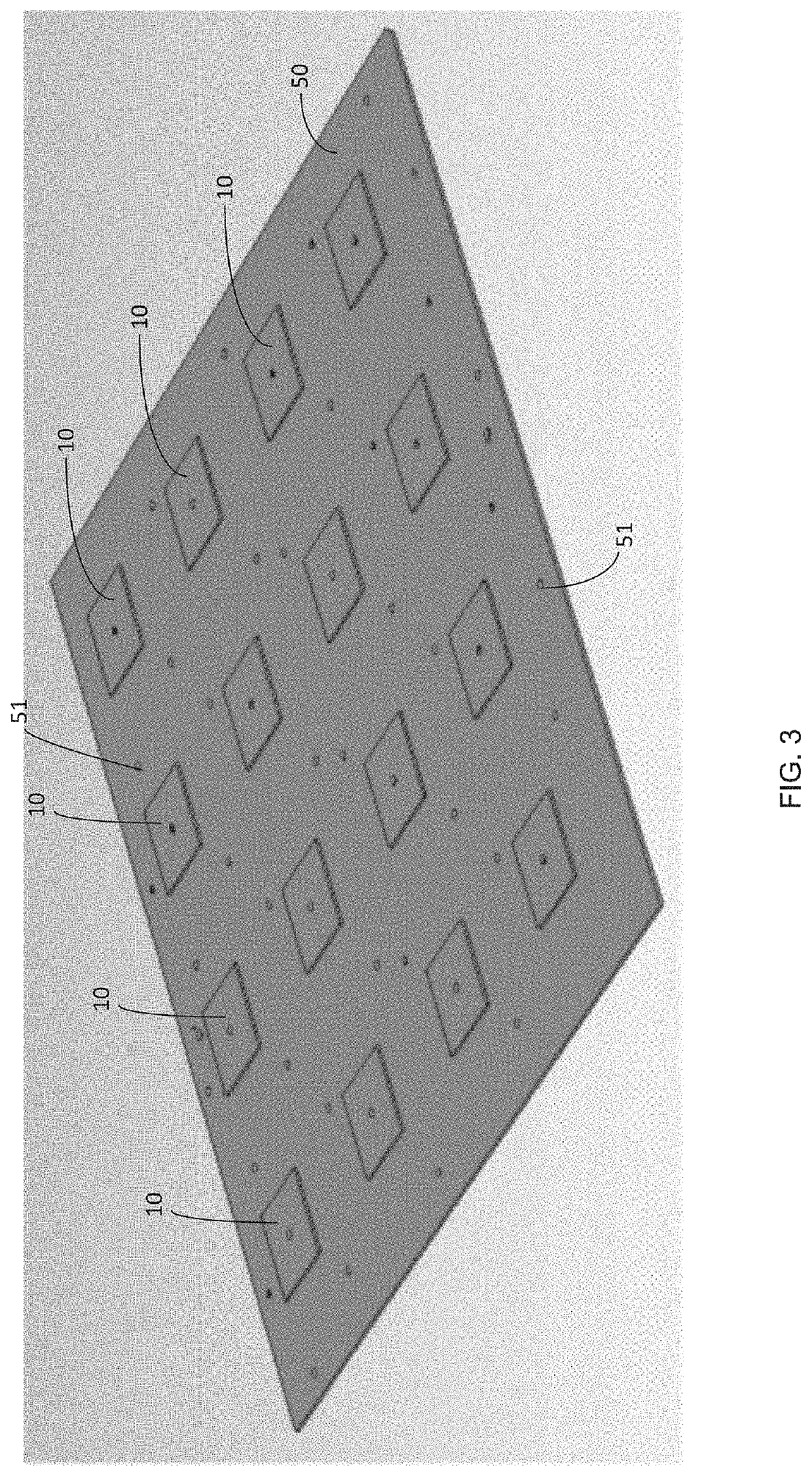
[0063]Referring to FIG. 3, a plurality of dual polarized patch antenna elements 10 and a ground plane 50 beneath the patch element 10 forms a patch element antenna array 100. There is a first air gap between the patch antenna element 10 and the ground plane 50. The air gap or air substrate functions as a dielectric. The antenna elements 10 are equally spaced apart from each other on the ground plane 50.

[0064]Referring to FIGS. 4, 5, 8 and 9, the 3D microstrip line feeding network 30, 40 helps the antenna 100 achieve very low side lobes and increase the antenna gain. The upper layer 80 of the 3D microstrip line feeding network 30, 40 provides a radiatio...


PUM


Abstract

An antenna assembly for transmitting or receiving radio waves, comprising: at least one patch antenna element; a three-dimensional (3D) microstrip line feeding network configured to feed the at least one patch antenna element for operation in dual polarisation, the 3D microstrip line feeding network comprising an upper layer and a lower layer; and a ground plane; wherein a first air gap is provided between the at least one patch antenna element and the ground plane, a second air gap is provided between the upper layer of the 3D microstrip line feeding network and the ground plane, and a third air gap is provided between the lower layer of the 3D microstrip line feeding network and the ground plane.

Description

CROSS-REFERENCES TO RELATED APPLICATIONS[0001]This application is a continuation application of International Patent Application No. PCT / AU2019 / 050244 entitled “ULTRA THIN AND COMPACT DUAL POLARIZED MICROSTRIP PATCH ANTENNA ARRAY WITH 3-DIMENSIONAL (3D) FEEDING NETWORK,” filed on Mar. 20, 2019, which claims priority to Australian Patent Application No. 2018900994, filed on Mar. 26, 2018, all of which are herein incorporated by reference in their entirety for all purposes.FIELD OF THE INVENTION[0002]The present invention relates to a dual polarized compact high gain patch antenna array having an ultra thin profile for a fixed wireless, cellular base station or indoor coverage application. The present invention provides a microstrip patch array antenna with 3-dimensional (3D) microstrip line feeding network to increase the array antenna gain by reducing the low side lobes, which is inexpensive to manufacture. In one example, the dual polarized compact high gain patch antenna array is ...

Claims


Application Information

Patent Timeline
Patent Type & Authority Patents(United States)
IPC IPC(8): H01Q21/00H01Q1/48H01Q21/06H01Q21/24H01Q9/04
CPCH01Q21/0075H01Q1/48H01Q9/0457H01Q21/065H01Q21/24H01Q9/0407H01Q21/28
Inventor WANG, DANIEL
Owner NETCOMM WIRELESS
Why Eureka
Try Eureka