
Method of making an electrochemical cell

a technology of electrochemical cells and electrodes, applied in the manufacture of electrodes, cell components, electrochemical generators, etc., can solve the problem that the manufacturing cost of solid oxide fuel cells is often high

Active Publication Date: 2022-09-06
HAMILTON SUNDSTRAND CORP
View PDF22 Cites 0 Cited by
  • Summary
  • Abstract
  • Description
  • Claims
  • Application Information

AI Technical Summary

Problems solved by technology

However, solid oxide fuel cell technology is often very costly to manufacture.

Method used


Image

  • Method of making an electrochemical cell
  • Method of making an electrochemical cell

Examples


Embodiment Construction

[0010]A detailed description of one or more embodiments of the disclosed apparatus and method are presented herein by way of exemplification and not limitation with reference to the Figures.

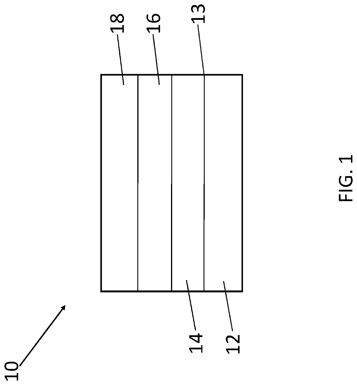
[0011]Referring to FIG. 1, an electrochemical cell 10 can include a porous metal support layer 12, an oxide protection layer 13, an anode layer 14, an electrolyte layer 16, and a cathode layer 18. For example, the electrochemical cell can be a solid oxide fuel cell, a solid oxide electrolysis cell, or a combination thereof.

[0012]The porous metal support layer 12 can comprise metal materials, metal ceramic composite materials, or combinations thereof. For example, the porous metal support layer 12 can comprise nickel, iron nickel alloy, nickel chromium aluminum yttrium, stainless steel, for example, ferritic stainless steel, or any combination thereof. The porous metal support layer 12 can have a porosity of about 10% to about 50% based on a total volume of the porous metal support layer 12. Poros...


PUM

PropertyMeasurementUnit
porosityaaaaaaaaaa
operating temperatureaaaaaaaaaa
diameteraaaaaaaaaa

Abstract

Disclosed is a method of making an electrochemical cell, comprising: depositing an anode layer on a surface of a porous metal support layer; depositing an electrolyte layer on a surface of the anode layer, wherein the electrolyte layer is deposited via suspension plasma spray, wherein the electrolyte layer conducts protons; and depositing a cathode layer on a surface of the electrolyte layer. Also disclosed is a stack comprising two or more of the electrochemical cell.

Description

STATEMENT OF FEDERAL SUPPORT[0001]This invention was made with Government support under contract DE-EE0008080 awarded by the Department of Energy. The Government has certain rights in the invention.BACKGROUND[0002]Exemplary embodiments pertain to the art of electrochemical cells, more particularly, to a method of making an electrochemical cell using suspension plasma spray.[0003]Oxide fuel cells have many potential applications. For example, in the aerospace industry, potential applications include electrolysis, auxiliary power generation, and aircraft propulsion. For example, solid oxide fuel cells are compatible with hydrocarbon fuels, such as methane, ethanol, and jet fuels. Metal-supported electrochemical cell stacks, enabled by proton-conducting electrolyte materials, can also provide fast startup times, fast transit response, and high power density. However, solid oxide fuel cell technology is often very costly to manufacture.[0004]Therefore, there is a need to develop a metho...

Claims


Application Information

Patent Timeline
Patent Type & Authority Patents(United States)
IPC IPC(8): H01M8/1226H01M4/04H01M4/134H01M10/0525
CPCH01M8/1226H01M4/0404H01M4/134H01M10/0525H01M8/1213H01M8/124H01M2008/1293H01M2300/0068Y02E60/10
Inventor ZHU, TIANLIHUMBERT, MICHAEL PAUL
Owner HAMILTON SUNDSTRAND CORP
Learn More