Supercharge Your Innovation With Domain-Expert AI Agents!

Slip ring body

a ring body and ring technology, applied in current collectors, dynamo-electric machines, electrical equipment, etc., can solve the problems of limiting the development of eddy currents, high cost, and high technical requirements for heat managemen

Active Publication Date: 2022-09-06
FLENDER GMBH
View PDF11 Cites 0 Cited by
  • Summary
  • Abstract
  • Description
  • Claims
  • Application Information

AI Technical Summary

Benefits of technology

The patent is about a new design for a slip ring body that reduces heat loss and improves efficiency compared to previous designs. This is achieved through a combination of lower magnetic conductivity (lowered magnetic permeability) and the presence of an air gap around the recess where the conductor bars are located. The reduced magnetic conductivity reduces eddy currents, which in turn reduces heat loss. Additionally, the use of a material with effective electrical conductivity helps to further reduce heat loss and improve efficiency.

Problems solved by technology

This is associated with high costs on the one hand and high technical requirements for the heat management on the other hand.
These are characterized by a comparatively low magnetic conductivity, which limits the development of eddy currents.
The costs of copper, however, are several orders of magnitude higher than those for stainless steel, which makes solutions of this kind less appealing from an economic perspective.

Method used


Image

  • Slip ring body
  • Slip ring body
  • Slip ring body

Examples


Embodiment Construction

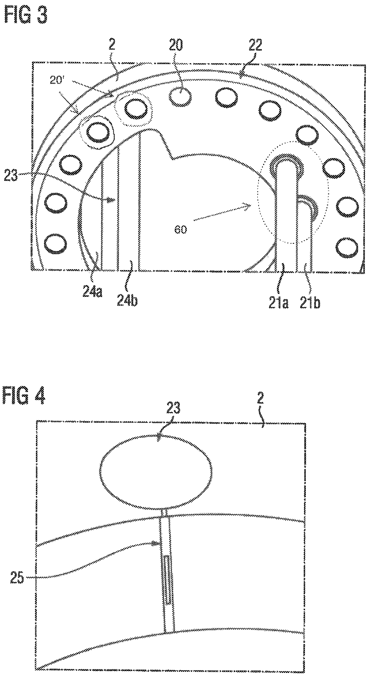
[0041]FIG. 3 shows a slip ring 2 of a slip ring body 1 according to the invention in an oblique view. The slip ring 2 is embodied as a hollow cylinder and has ventilation holes 20 distributed over its perimeter that are used for passive heat dissipation of the slip ring 2 when the slip ring 2 is made to rotate, FIG. 3 also shows 20′ in the upper left corner of FIG. 3 deepened parts around two of the recesses 20 that are incorporated leading to a smaller thickness than other parts of the silo ring 2. The deepened part is illustrated such that the smaller thickness can be seen at least at the outer rim of the slip ring 2.

[0042]Two conductor bars 21a, 21b are fastened to the slip ring 2 in a region 60. The fastening may be implemented by means of screwing or pressing the conductor bars 21a, 21b to or into the slip ring 2, for example. The conductor bars 21a, 21b are used for transmitting energy from an outer side 22 of the slip ring 2 to an electric machine (not shown), in particular a...


PUM


Abstract

A slip ring body for electrically contacting an asynchronous machine includes first and second slip rings rigidly connected to one another, with at least two conductor bars fastened to each of the slip rings. At least one of the slip rings has a recess for passage of the conductor bars of the other slip ring and defining around the recess a first region in which air is at least partially present and which has a magnetic conductivity that is lower than a magnetic conductivity in a second region in which the conductor bars to the one slip ring are fastened, or which second region is embodied for contacting with an energy-transmitting brush. The first and second regions are not made of copper. The recess defines an opening cross-sectional area which is greater than a cross-sectional area of the conductor bars fastened to the one slip ring.

Description

CROSS-REFERENCES TO RELATED APPLICATIONS[0001]This application is the U.S. National Stage of International Application No. PCT / EP20191072673, filed Aug. 26, 2019, which designated the United States and has been published as International Publication No. WO 20201043648 A1 and which claims the priority of European Patent Application, Serial No. 18190980.5, filed Aug. 27, 2018, pursuant to 35 U.S.C. 119(a) (d).BACKGROUND OF THE INVENTION[0002]The invention relates to a slip ring body for electrically contacting an asynchronous machine as claimed in claim 1. In addition, the invention relates to an electric machine, in particular an asynchronous machine, with a slip ring body as claimed in claim 8. Furthermore, the invention relates to a use of a slip ring body for electrically contacting an asynchronous machine as claimed in claim 9.[0003]In doubly fed asynchronous machines, a three-phase current system is impressed in the rotor. For current transmission purposes, a slip ring transmitt...

Claims


Application Information

Patent Timeline
Patent Type & Authority Patents(United States)
IPC IPC(8): H01R39/10H01R39/02H02K9/28
CPCH01R39/10H01R39/025H02K9/28H01R39/08
Inventor BINDER, HERBERTGRUBER, ROBERTMEMMINGER, OLIVEROBERNEDER, MANUELSCHIFFERER, KLAUS
Owner FLENDER GMBH
Features
  • R&D
  • Intellectual Property
  • Life Sciences
  • Materials
  • Tech Scout
  • Unparalleled Data Quality
  • Higher Quality Content
  • 60% Fewer Hallucinations
Learn More