Patient connector assembly with vertical detents

a connector and vertical technology, applied in the direction of diagnostic recording/measure, coupling device connection, application, etc., can solve the problems of difficult manufacturing of connector assemblies using fasteners, such as screws, and errors in conventional pulse oximetry, so as to improve the overall construction of the connector assembly and facilitate the manufacturing process. the effect of quick and easy

Active Publication Date: 2022-09-20
MASIMO CORP
View PDF1093 Cites 39 Cited by
  • Summary
  • Abstract
  • Description
  • Claims
  • Application Information

AI Technical Summary

Benefits of technology

[0008]The retainer and the bottom and top connector tabs can together provide an improved overall construction of the connector assembly. Connector assemblies can often be relatively small, and the manufacturing of connector assemblies using fasteners, such as screws, that may utilize tools, such as screwdrivers, can be difficult. The retainer and connector tabs disclosed herein, however, can be assembled simply by pushing the retainer downward to fixedly mate the bottom and top connector tabs, so the manufacturing process can be easy and quick.
[0015]In some embodiments, a method of manufacturing a connector assembly for a noninvasive sensor assembly is disclosed. The method can include: placing a circuit board and a portion of conductors on an inner surface of a first connector tab having a plurality of catches; placing a second connector tab on top of the first connector tab so that an inner surface of the second connector tab can face the inner surface of the first connector tab, the second connector tab having a plurality of openings; and extending a retainer that can include a plurality of pins having a plurality of detents through the plurality of openings so that the plurality of detents can engage the plurality of catches.

Problems solved by technology

During patient motion, venous blood also moves, which causes errors in conventional pulse oximetry.
Connector assemblies can often be relatively small, and the manufacturing of connector assemblies using fasteners, such as screws, that may utilize tools, such as screwdrivers, can be difficult.

Method used


Image

  • Patient connector assembly with vertical detents
  • Patient connector assembly with vertical detents
  • Patient connector assembly with vertical detents

Examples


Embodiment Construction

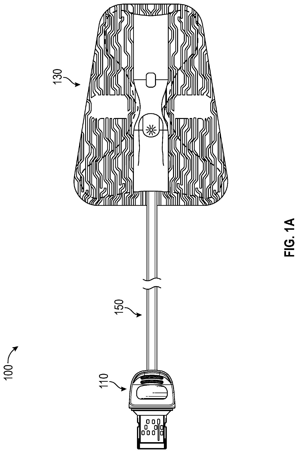
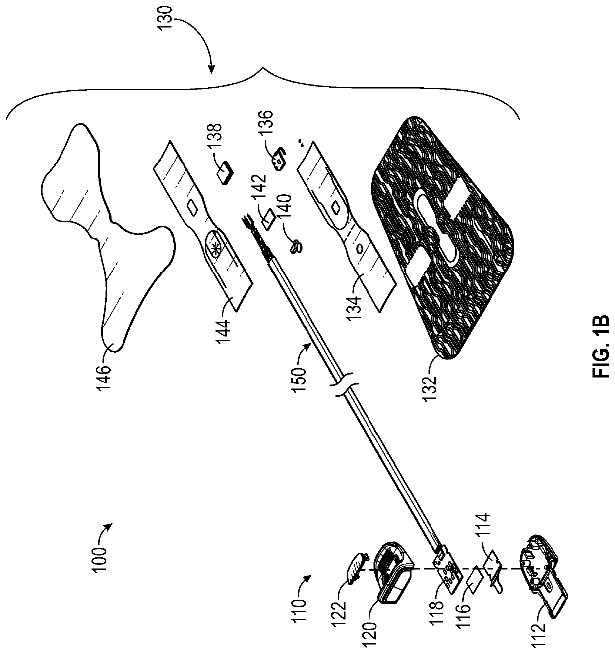
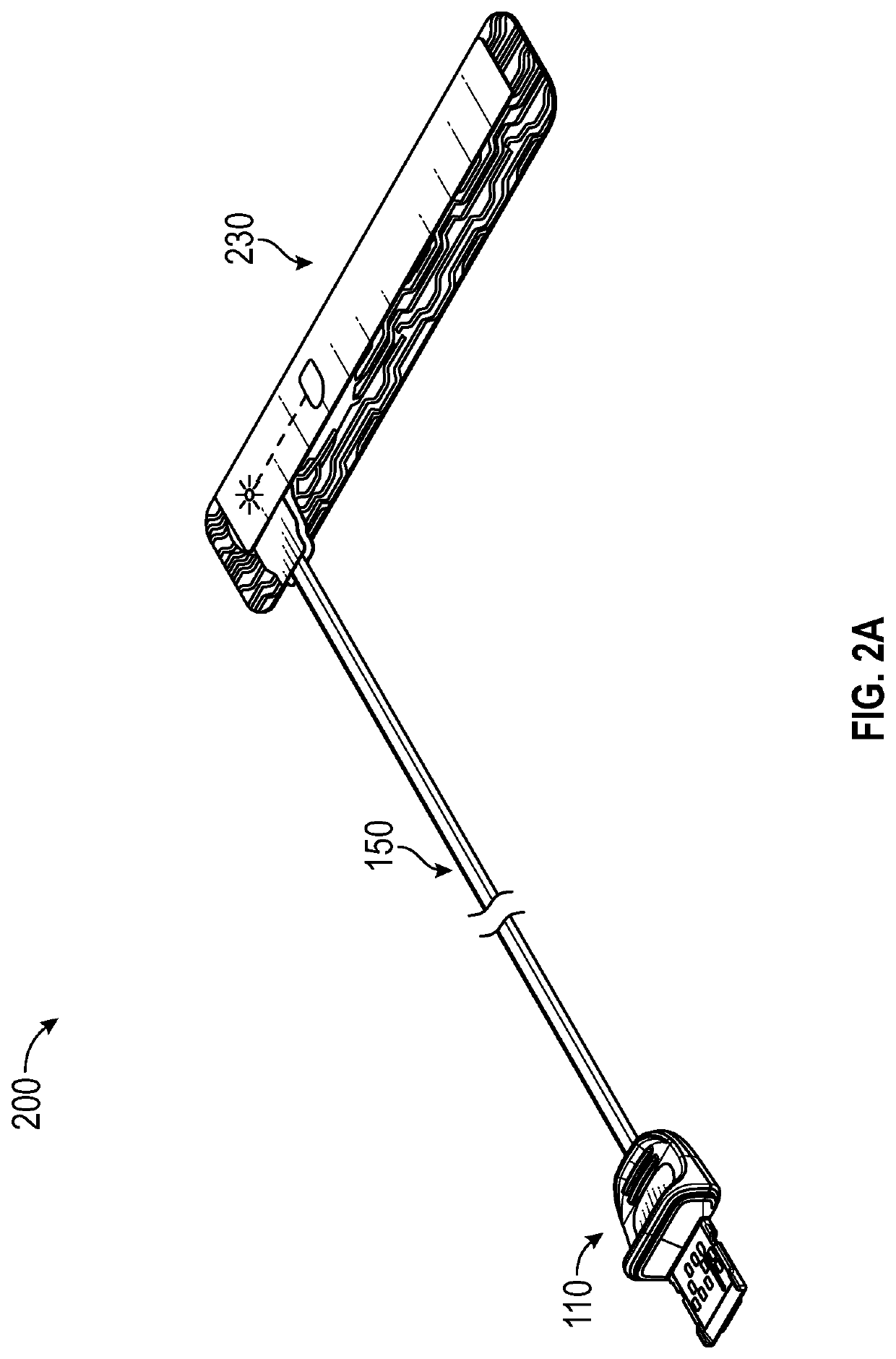
[0031]A connector assembly is disclosed that can be part of a sensor assembly usable to collect patient physiological data. The connector assembly can include first and second connector tabs, and a circuit board of a cable assembly for the sensor assembly placed between the first connector tab and the second connector tab. The connector assembly can further include a retainer that can extend through the second connector tab and be coupled to the first connector tab to secure the first and second connector tabs together. The sensor assembly can include a noninvasive sensor that may be positioned proximate to a patient's skin for generating the patient physiological data.

[0032]The first connector tab can include catches disposed on an inner surface of the first connector tab. The second connector tab can include openings, where the openings correspond to the catches. The retainer can include pins, where each of the pins correspond to the openings and the catches of the second and firs...


PUM


Abstract

The present disclosure includes a connector assembly that is a part of a sensor assembly for collecting patient physiological data. The connector assembly can include a first connector tab with catches, a second connector tab with openings, a retainer with pins, and a circuit board coupled to a cable. Each of the pins of the retainer can include a detent that can engage one of the catches of the first connector tab. The pins can extend through the openings of the second connector tab so that the retainer is coupled to the first connector tab by the detents engaging the catches. The first and second connector tabs can thereby be coupled together to support the circuit board and the cable between the first and second connector tabs.

Description

RELATED APPLICATIONS[0001]This application claims the benefit of U.S. Provisional Application No. 62 / 744,456, filed Oct. 11, 2018; the disclosure of which is hereby incorporated by reference in its entirety.BACKGROUNDField of Disclosure[0002]The disclosure related to improving the efficiency of manufacturing connector assemblies for sensor assemblies that collect patient physiological data.Description of the Related Art[0003]Pulse oximetry is a widely accepted noninvasive procedure for measuring the oxygen saturation level of arterial blood, an indicator of a person's oxygen supply. A typical pulse oximetry system utilizes an optical sensor clipped onto a fingertip to measure the relative volume of oxygenated hemoglobin in pulsatile arterial blood flowing within the fingertip. Oxygen saturation (SpO2), pulse rate, and a plethysmograph waveform, which is a visualization of pulsatile blood flow over time, are displayed on a monitor accordingly.[0004]Conventional pulse oximetry assumes...

Claims


Application Information

Patent Timeline
Patent Type & Authority Patents(United States)
IPC IPC(8): A61B5/1455A61M16/08A61B5/024A61B5/00
CPCA61B5/14551A61B5/02444A61B5/6826A61M16/0816A61B2562/166A61B2562/227A61B2562/228H01R13/508H01R13/6658H01R12/718H01R12/72H01R12/53A61B5/02416A61B5/1455H01R2201/12H01R24/62H01R43/18A61B5/02427A61B5/14552
Inventor SCRUGGS, STEPHENABDUL-HAFIZ, YASSIR KAMELAL-ALI, AMMARLAIDET, MARC ANTOINE
Owner MASIMO CORP
Why Eureka
Try Eureka