

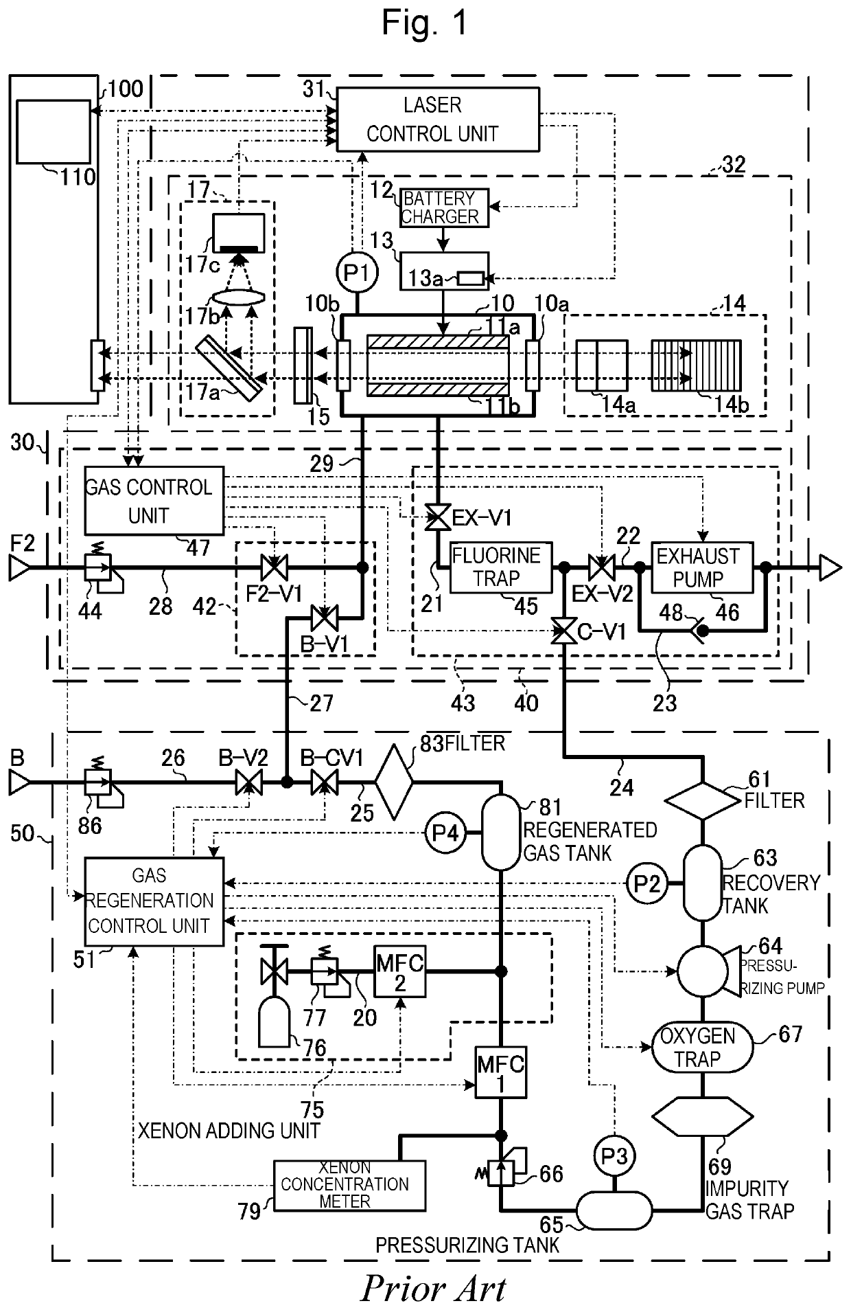
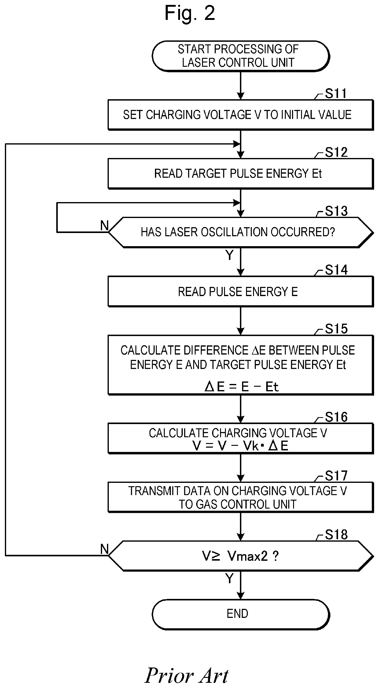
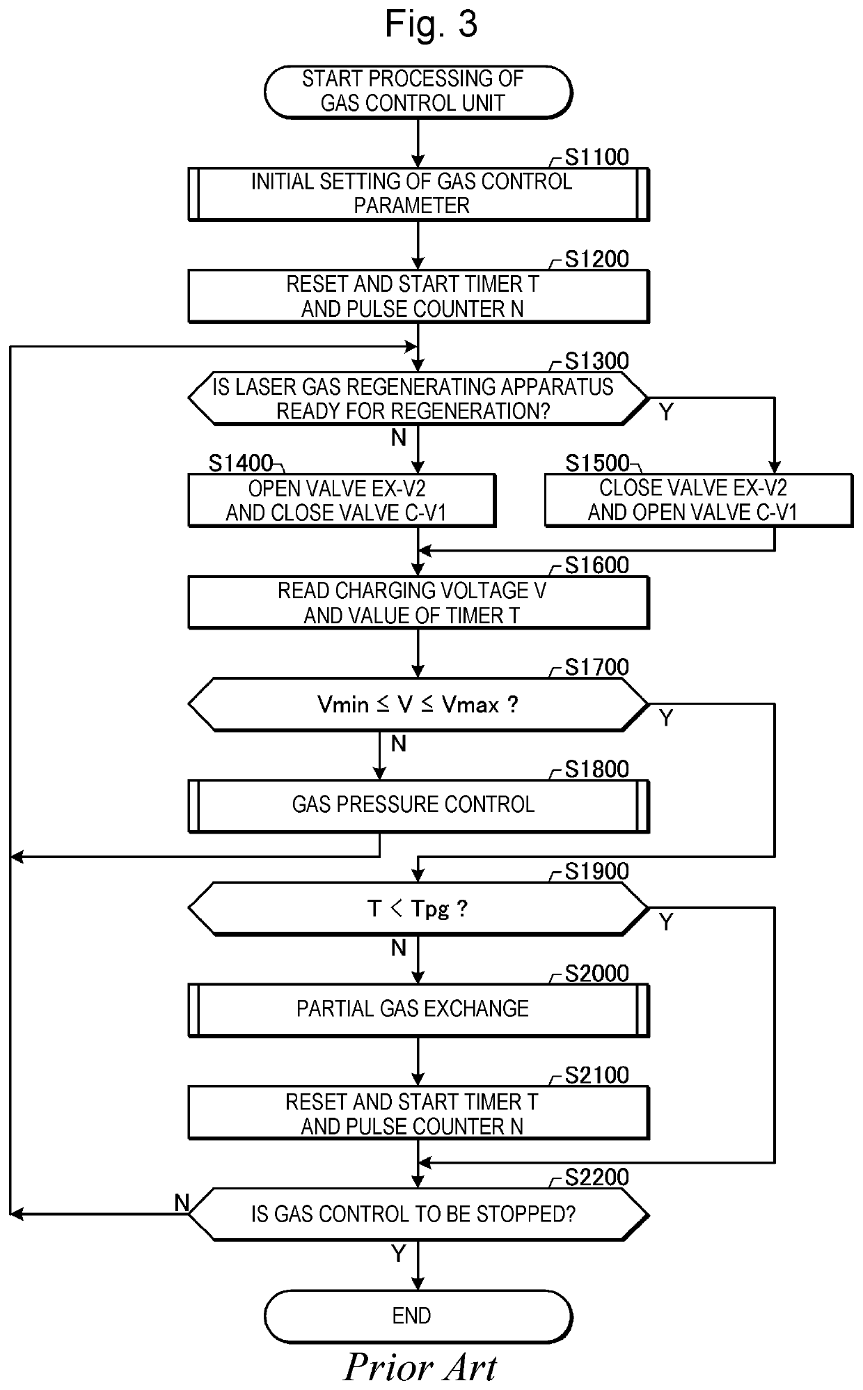
Laser gas regenerating apparatus and electronic device manufacturing method
a gas regenerating apparatus and gas technology, applied in the direction of photomechanical equipment, instruments, optics, etc., can solve problems such as reducing resolution
- Summary
- Abstract
- Description
- Claims
- Application Information
AI Technical Summary
Benefits of technology
Problems solved by technology
Method used
Image

Examples
first example
9.1 First Example
[0475]9.1.1 Configuration
[0476]FIG. 31 schematically Shows a First Example of a regenerated gas tank that can be used in the embodiments. A regenerated gas tank 81a in FIG. 31 includes a container 811, and an insert pipe 812 and a lead-out pipe 813 inserted into the container 811. An inert gas pressure sensor P4 is further connected to the container 811.
[0477]One end of the insert pipe 812 is located outside the container 811, and the other end of the insert pipe 812 is located inside the container 811. In the container 811, the insert pipe 812 has many through holes.
[0478]One end of the lead-out pipe 813 is located outside the container 811, and the other end of the lead-out pipe 813 is located inside the container 811.
[0479]9.1.2 Operation and Effect
[0480]The inert regenerated gas introduced from the one end of the insert pipe 812 is ejected from the insert pipe 812 through the many through holes into the container 811 in various directions. This causes a complex ...
second example
9.2 Second Example
[0484]9.2.1 Configuration
[0485]FIG. 32 schematically shows a second example of a regenerated gas tank that can be used in the embodiments. A regenerated gas tank 81b in FIG. 32 includes a container 814, a gas introducing pipe 815 and a gas lead-out pipe 816 inserted into the container 814, and a propeller shaft 817. An inert gas pressure sensor P4 is further connected to the container 814.
[0486]One end of each of the gas introducing pipe 815 and the gas lead-out pipe 816 is located outside the container 814, and the other end of each of the gas introducing pipe 815 and the gas lead-out pipe 816 is located inside the container 814.
[0487]One end of the propeller shaft 817 is located outside the container 814, and the other end of the propeller shaft 817 is located inside the container 814. In the container 814, a propeller 818 is mounted to the propeller shaft 817. Outside the container 814, a motor 819 is mounted to the propeller shaft 817. The propeller shaft 817, ...
PUM
| Property | Measurement | Unit |
|---|---|---|
| wavelength | aaaaa | aaaaa |
| wavelength | aaaaa | aaaaa |
| wavelength | aaaaa | aaaaa |
Abstract
Description
Claims
Application Information