Power storage module and power supply system

a power storage module and power supply technology, applied in secondary cells, battery servicing/maintenance, instruments, etc., can solve the problems of large size of the entire module, including the battery pack and the heater, and achieve the effect of increasing the switching frequency, increasing the temperature of the secondary battery, and increasing the temperature quickly

Active Publication Date: 2022-10-04
MURATA MFG CO LTD
View PDF16 Cites 0 Cited by
  • Summary
  • Abstract
  • Description
  • Claims
  • Application Information

AI Technical Summary

Benefits of technology

[0006]Accordingly, the exemplary embodiments of the present invention have been made in view of the above reason. Thus, it is an object of the present invention is to provide a power storage module and a power supply system that are miniaturized while preventing an excessive temperature drop in a secondary battery.
[0014]According to exemplary embodiments of the present invention, when a temperature of the secondary battery needs to be increased, the control unit forces the bidirectional DC-DC converter to operate in the discharge mode and increases the switching frequency of the switching element. Thereby, an amount of heat generated by the switching element is increased, and an amount of heat transmitted from the switching element to a periphery of the secondary battery is increased, so that the temperature of the secondary battery can be increased quickly. Therefore, since there is no need to arrange a heater in the periphery of the secondary battery in order to quickly increase the temperature in the periphery of the secondary battery, it is possible to reduce an entire size of the power storage module.

Problems solved by technology

However, with the configuration described in Patent Document 1, since it is necessary to arrange the heater in the container, the entire module including the battery pack and the heater is large.

Method used


Image

  • Power storage module and power supply system
  • Power storage module and power supply system
  • Power storage module and power supply system

Examples


Embodiment Construction

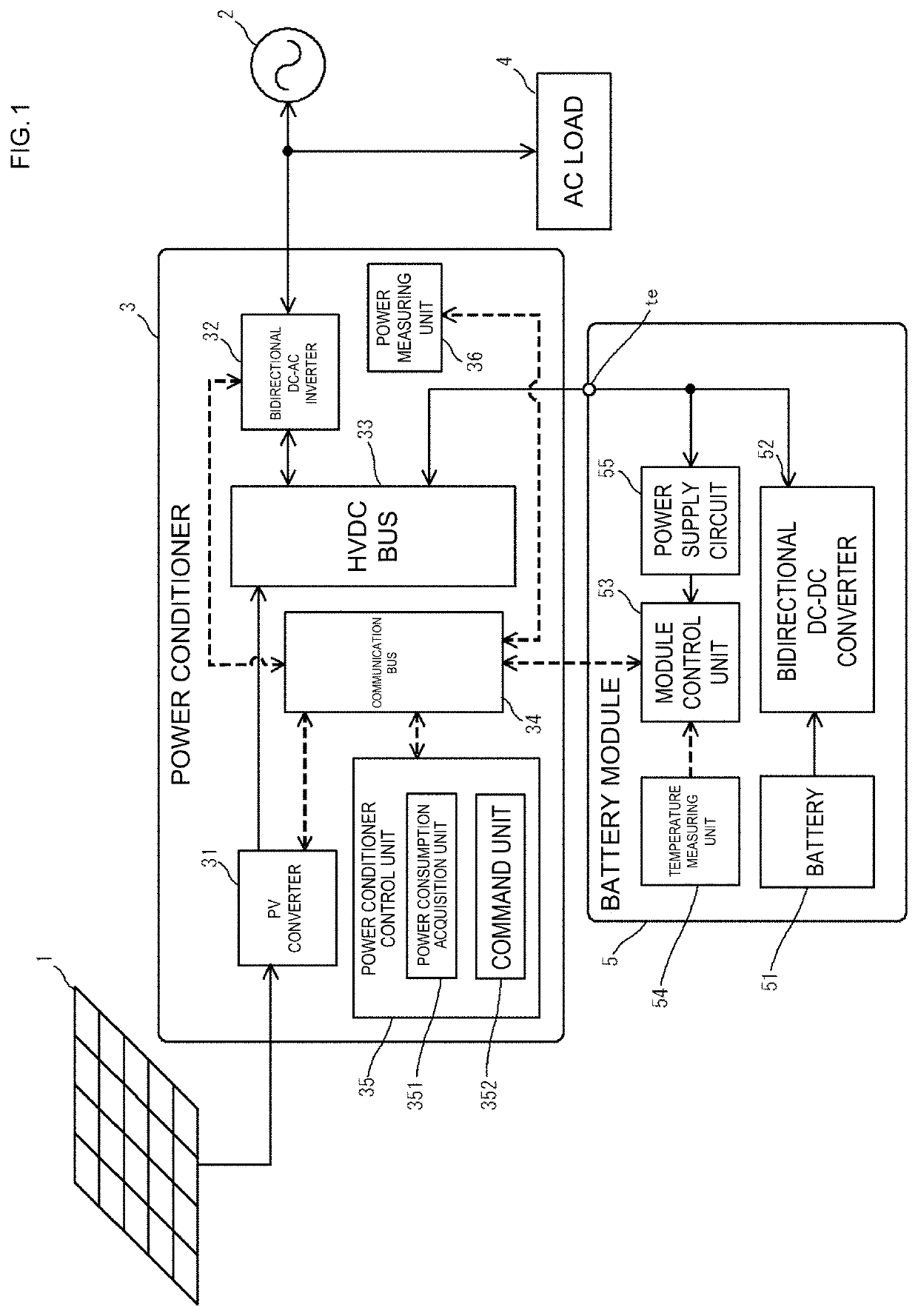
[0028]Hereinafter, an exemplary embodiment of the present invention will be described in detail with reference to the accompanying drawings. As described herein, a power supply system is provided that is a distributed power supply system, and supplies power to an AC load from a solar battery or a secondary battery in interconnection with a power system. The exemplary power supply system includes a power conditioner and a power storage module connected to the power conditioner. The power conditioner includes a bidirectional DC-AC inverter configured to convert AC power supplied from the power system into DC power to supply the DC power to a DC bus line, and to convert DC power supplied from the DC bus line into AC power to supply the AC power to the AC load connected to the power system. The power storage module includes a secondary battery, a bidirectional DC-DC converter interposed between the secondary battery and an input / output unit connected to the DC bus line, and a control un...


PUM

PropertyMeasurementUnit
voltageaaaaaaaaaa
output voltageaaaaaaaaaa
temperatureaaaaaaaaaa

Abstract

A battery module that includes a battery and a bidirectional DC-DC converter including a switching element that is arranged at a position where heat generated by the switching element is transmitted to the battery. The bidirectional DC-DC converter operates in a discharge mode in which DC power supplied from the battery is converted and supplied to an input / output unit, and in a charge mode in which DC power supplied from the input / output unit is converted and supplied to the battery. Moreover, a control unit forces the bidirectional DC-DC converter to operate in the discharge mode and to increase a switching frequency of the switching element in comparison with a switching frequency in normal driving, when a temperature in a periphery of the battery needs to be increased.

Description

CROSS REFERENCE TO RELATED APPLICATIONS[0001]The present application is a continuation of PCT / JP2018 / 038364 filed Oct. 15, 2018, which claims priority to Japanese Patent Application No. 2017-220643, filed Nov. 16, 2017, the entire contents of each of which are incorporated herein by reference.TECHNICAL FIELD[0002]The present invention relates to a power storage module and a power supply system.BACKGROUND[0003]Currently there are proposed temperature regulation devices that are for a battery pack and that include a fan for guiding air into a container housing a plurality of batteries and a heater for heating the air (see, for example, Patent Document 1, identified below). In an example configuration, the temperature regulation device for the battery pack includes a temperature sensor for detecting a temperature of each of a plurality of batteries, and a temperature control means for adjusting a temperature of the battery pack based on the temperature detected by the temperature senso...

Claims


Application Information

Patent Timeline
Patent Type & Authority Patents(United States)
IPC IPC(8): H02J7/06H02M3/158H02J7/00H02J7/35H01M10/44H01M10/615H01M10/627H01M10/633H01M10/667H01M10/48
CPCH02J7/06H01M10/44H01M10/486H01M10/615H01M10/627H01M10/633H01M10/667H02J7/0047H02J7/35H02M3/158H01M2220/10H02J2207/20Y02E60/10H01M10/425H01M10/63H01M10/0525H02M7/66H02M1/36H02J2300/24H02J3/32H02J7/007194Y02E10/56H02M1/0009H02M1/008
Inventor TAGAWA, SHUICHITAKEI, YOUSUKE
Owner MURATA MFG CO LTD
Why Eureka
Try Eureka