
Eureka
For R&D, Eureka makes reading and utilizing patents & technical documents easy.
Eureka AIR
Designed for self-driven R&D workflows. Generate viable solutions, solve complex R&D challenges, empower your innovation with AI.

Eureka Materials
Designed for material experts only. Revolutionize your material R&D, from search, analyze, to developing new materials.

TechResearch
Generate reliable direction feasibility study reports for your R&D in just a few steps.

TechSeek
Discover and master advanced knowledge NOW. Basics, ideas, possibilities, all at once.

TechMind
As an expert in R&D Theories, TechMind can generates customized viable solutions instantly.

TechRisk
Analyze your overall solution with one click, know your potential R&D risks in advance.

TechMonitor
Get weekly tech updates, stay abreast of the latest tech innovations and key insights.
Applicator device
- Summary
- Abstract
- Description
- Claims
- Application Information
AI Technical Summary
Benefits of technology
Problems solved by technology
Method used
Image

Examples
2nd example
2nd Example
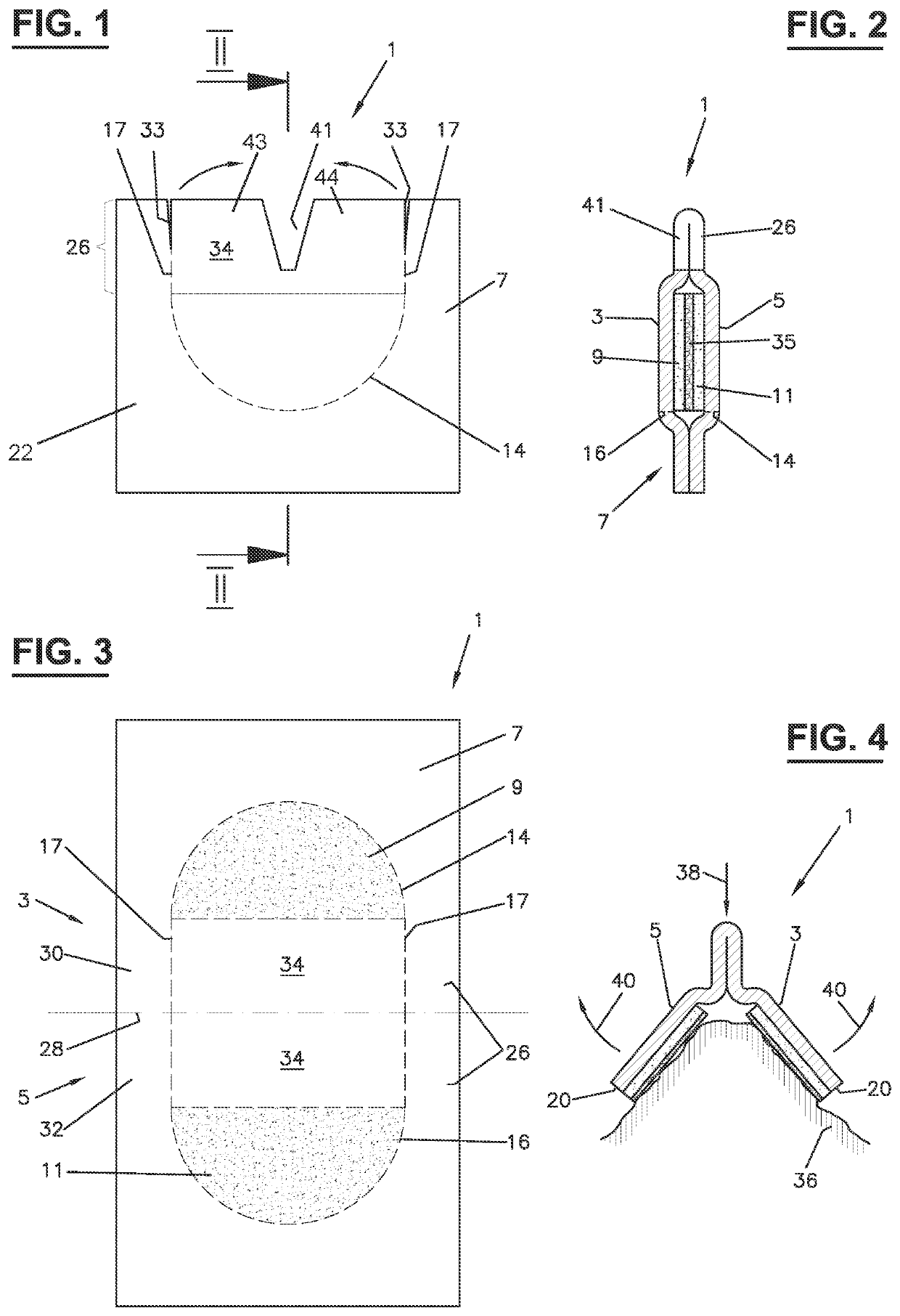
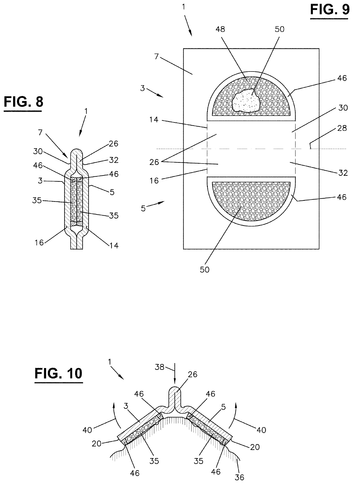
[0068]Sometimes a device is required to apply an agent to a surface, e.g. the skin, yet a mechanical interaction with the surface is not required. Or the agent has such properties, that pads 9, 11 are not required or even disadvantageous.
[0069]A suitable applicator device 1 (cf. FIGS. 8-10) for such situations is provided with a rib 46 running along each weakening line 14, 16. Preferably the ends are closed so to form a basin 48 on the upper and lower wing 3, 5 of the carrier sheet 7. The interior of the basin 48 may be filled with the agent, either completely (cf. FIG. 8) or only partly, i.e. up to a level lower than the height of the rib 46. The basin 48 may contain a pad 50, too, of a material suited for pad 9, 11 of the first execution example. As the rib 46 is securing that the edge 20 of the carrier sheet 7 does not get in contact with the surface 36, the pad 50 arranged in the basin 48 may have any shape and may fill only a part of the basin 48. In particular, the ...
first embodiment
[0072]The applicator according to this embodiment may furthermore correspond in any other aspect to the In particular, the cut-out or notch 41 may be provided in order to allow a forced spreading of the wings in use as set forth above.
[0073]For this example, too, the recess may even be lower down to zero if the height of the elevation 46 is properly chosen. In particular, the same considerations and dimensions are applicable as set forth above for a weakening line at least partially exactly following the contour of pads 9, 10 with respect to FIG. 11.
[0074]As FIG. 10 illustrates, it is even possible to set the rim of the carrier sheet 7, i.e. the main weakening lines14, 16, back with respect to the rim of the rib 46, provided that the rib is not or only weakly connected (glued, welded etc.) with the part of the carrier sheet outside the main weakening line, so that this part of the carrier sheet may be ripped off without damaging the rib 46. The distance by which the main weakening ...
PUM
 Abstract
Description
Claims
Application Information
 - R&D Engineer
- R&D Manager
- IP Professional
- Industry Leading Data Capabilities
- Powerful AI technology
- Patent DNA Extraction
Browse by: Latest US Patents, China's latest patents, Technical Efficacy Thesaurus, Application Domain, Technology Topic, Popular Technical Reports.
© 2024 PatSnap. All rights reserved.Legal|Privacy policy|Modern Slavery Act Transparency Statement|Sitemap|About US| Contact US: help@patsnap.com