Photovoltaic element

Inactive Publication Date: 2001-08-23
EVONIK ROEHM GMBH
View PDF0 Cites 30 Cited by
  • Summary
  • Abstract
  • Description
  • Claims
  • Application Information

AI Technical Summary

Problems solved by technology

This fixation method is expensive, however.
Above and beyond this, especially under conditions of prolonged exposure, the danger exists that the embedding medium will interact chemically with the embedded cells, possibly destroying the cells.
Furthermore, impact loads are transmitted from the

Method used


Image

  • Photovoltaic element
  • Photovoltaic element

Examples


Embodiment Construction

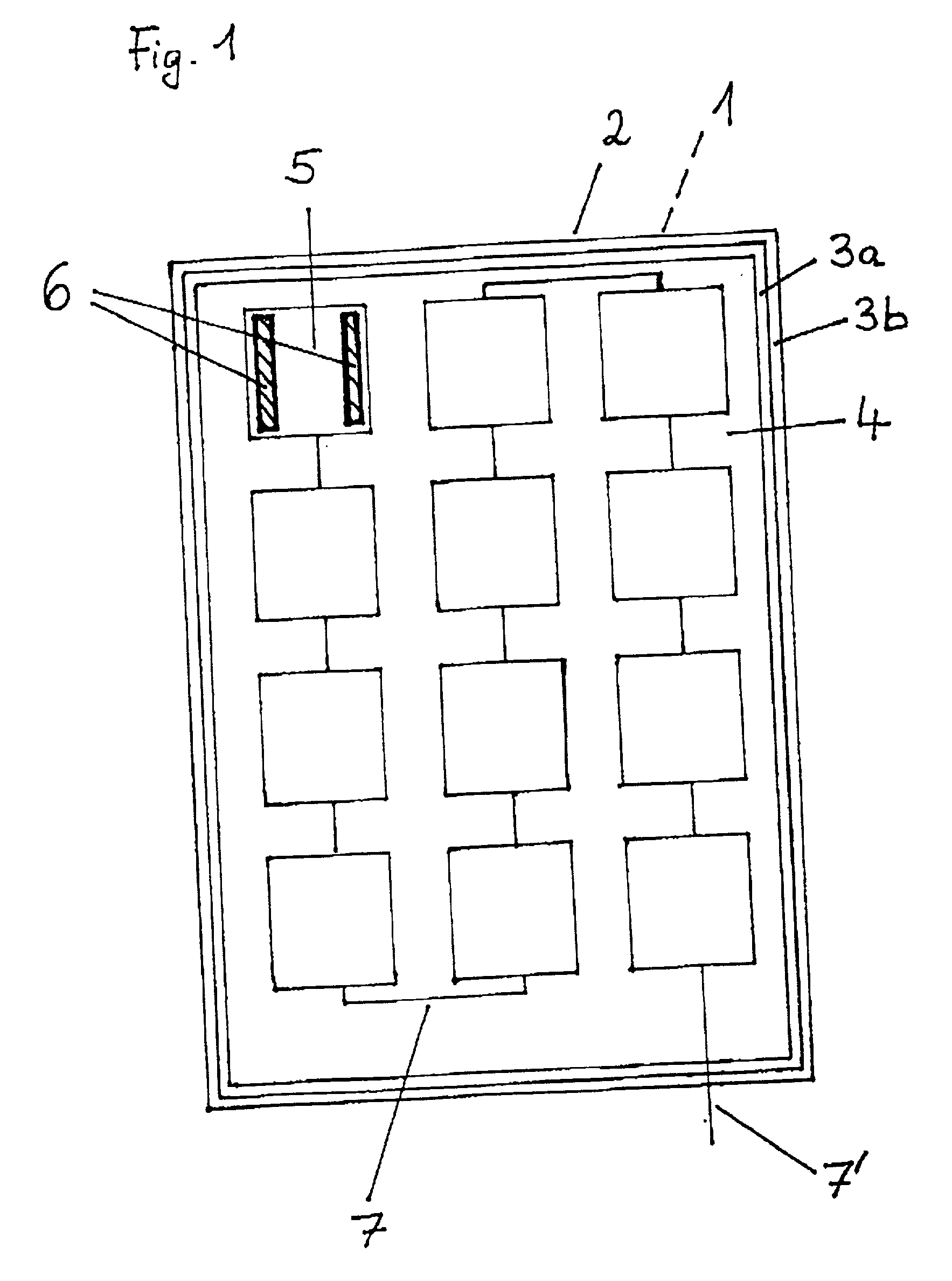
[0052] In a preferred arrangement, a plurality of photovoltaic cells (5), for example an array of 10.times.10 cells with intermediate spacings of about 1 cm, were fixed on a polymethyl methacrylate plate (2) with a surface area of 150.times.150 cm and a thickness of 1 cm, using for each two transparent adhesive strips (6) measuring, for example, 0.5.times.5 cm and comprising double-sided elastic acrylate adhesive tape, the cells being connected by conductor tracks (7).

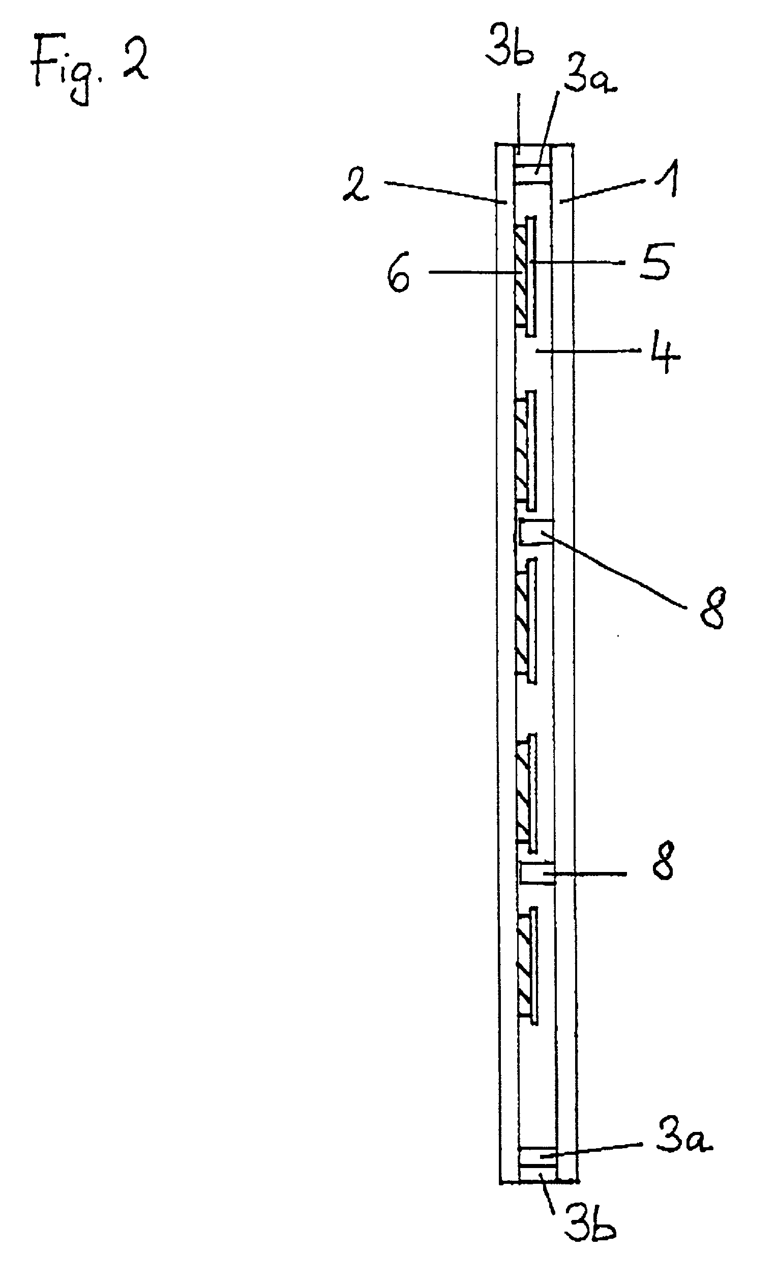
[0053] Current-collecting cable (7') of the electric cell assembly was brought out on one side. For the sake of clarity, the outgoing cabling of the first cell is not shown. A plurality of polymethyl methacrylate spacer pads (8) measuring 1.times.1 cm and having a thickness of 1 mm were attached adhesively by moistening the interface to plate (2) with methylene chloride.

[0054] A barrier layer (3a) comprising a compliant acrylate adhesive (polyethyl acrylate dissolved in ethyl acetate) was now applied on the assembly of...


PUM


Abstract

A photovoltaic element having two plane or curved plates (1) and (2), which are joined by a circumferential seal (3) at a spacing ranging from 2 to 20 mm, thus forming a cavity (4) in which there are enclosed a plurality of photovoltaic cells (5), each of which is attached to only one of the two plates (2) using an adhesive (6), at least this plate (2) being transparent, wherein both plates are made of plastic that is permeable to water vapor and the adhesive with which the photovoltaic cells are attached covers at most 30% of the area of the individual photovoltaic cells can be used for applications such as roofing and illuminating bus stops.

Description

[0001] 1. Field of the Invention[0002] The invention relates to a photovoltaic element in which a plurality of photovoltaic cells are enclosed between two plastic plates.[0003] 2. Discussion of the Background[0004] Photovoltaic elements containing photovoltaic cells embedded in plastic between transparent panes are generally known. These elements are used for applications such as roofing and illuminating bus stops.[0005] German Patent Application 4443317 describes a photovoltaic element in which a plurality of photovoltaic cells are embedded in an elastic plastic material between two polymethyl methacrylate plates. The photovoltaic cells are protected against ingress of water and against mechanical influences, such as impacts.[0006] German Patent Application 3801989 describes a cladding panel of insulating glass in which photovoltaic solar generators in the air space between two glass panes are attached to one of the panes using an elastic plastic. Thereafter the solar generator is ...

Claims


Application Information

Patent Timeline
IPC IPC(8): H01L31/042C09J4/02E04D13/18H01L31/04H01L31/048H01L31/049
CPCH01L31/048Y02B10/12Y02E10/50H01L31/0481H01L31/049Y02B10/10
Inventor BENZ, VOLKERBLUMENSCHEIN, MICHAELKRALL, MARKUS
Owner EVONIK ROEHM GMBH
Why Eureka
Try Eureka