Rotary drag-type drill bits and methods of designing such bits

Inactive Publication Date: 2001-09-13
CAMCO INT
View PDF0 Cites 22 Cited by
  • Summary
  • Abstract
  • Description
  • Claims
  • Application Information

AI Technical Summary

Problems solved by technology

It is well known that rotary drag-type drill bits may under certain conditions, particularly at low rotary speeds, and high weight-on-bit, be subject to torsional vibration as a result of a phenomenon commonly referred to as "stick-slip".
In stick-slip the situation arises where the bottomhole assembly is rotating more slowly than the upper end of the drill string due, for example, to frictional torque acting on the bottomhole assembly, with the result that the drill string begins to wind up.
This transfer of torsional energy from the drill string to the bottomhole assembly can occur periodically giving rise to torsional vibrations.
Such torsional vibration is undesirable s

Method used


Image

  • Rotary drag-type drill bits and methods of designing such bits
  • Rotary drag-type drill bits and methods of designing such bits
  • Rotary drag-type drill bits and methods of designing such bits

Examples


Example

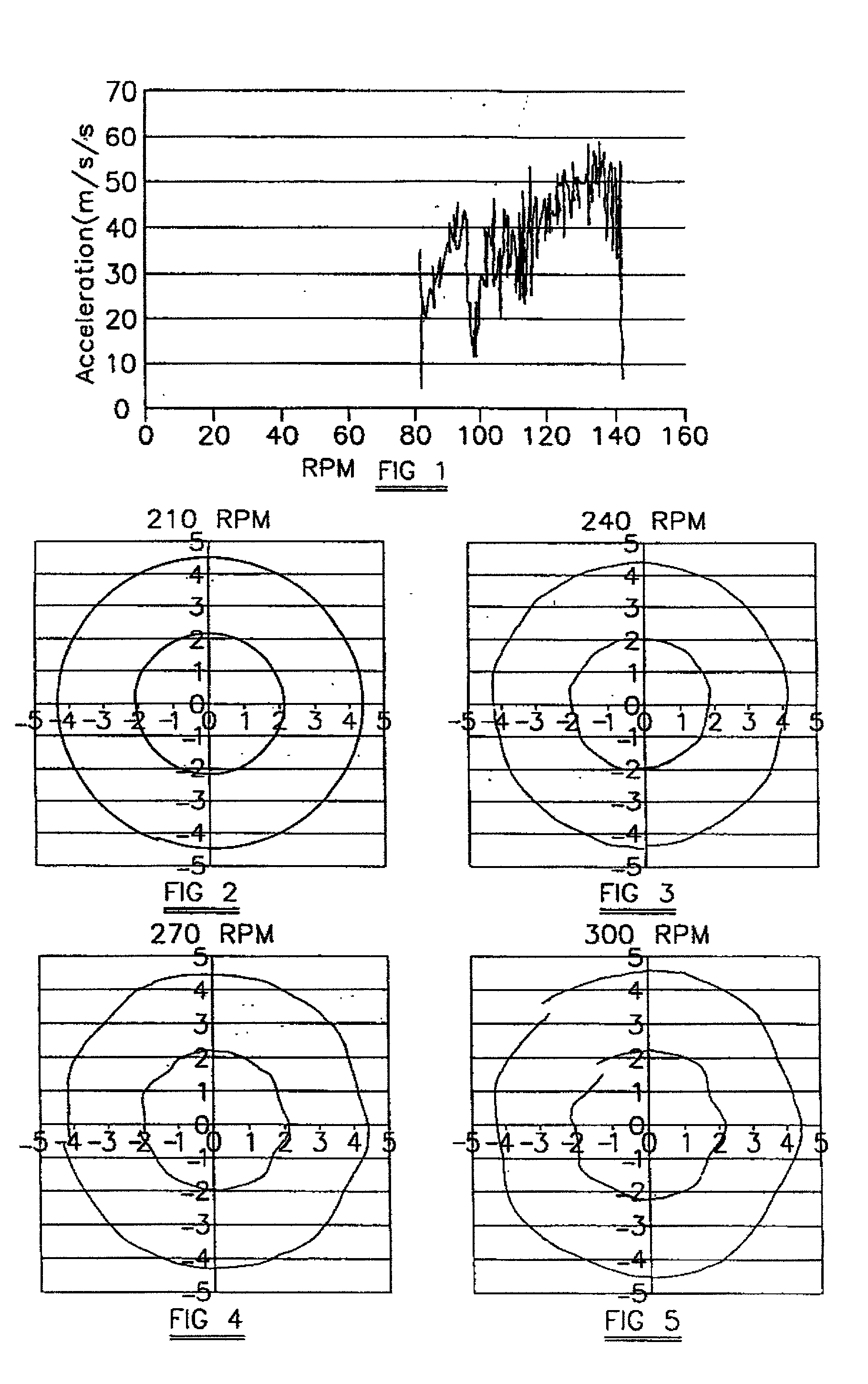
[0045] FIG. 1 shows the lateral vibration of a particular drag-type rotary drill bit (Bit A) plotted against rpm, the vibration being plotted as lateral acceleration in meters / s / s, and the data being acquired in laboratory drilling tests. This shows that Bit A is not stable, experiencing lateral vibration that rises quickly with rotary speed to 60 m / s / s. However, contrary to the conventional teaching in the drill bit art, which considers that bit stability is required in order to reduce torsional vibrations, Bit A is found to exhibit a very low incidence of stick-slip while drilling.

[0046] This characteristic has been found in other PDC drill bits; and FIGS. 2-5 show the patterns of lateral vibration in an 81 / 2 inch unbalanced drill bit (Bit B) with increase of rotary bit speed from 210 rpm to 300 rpm.

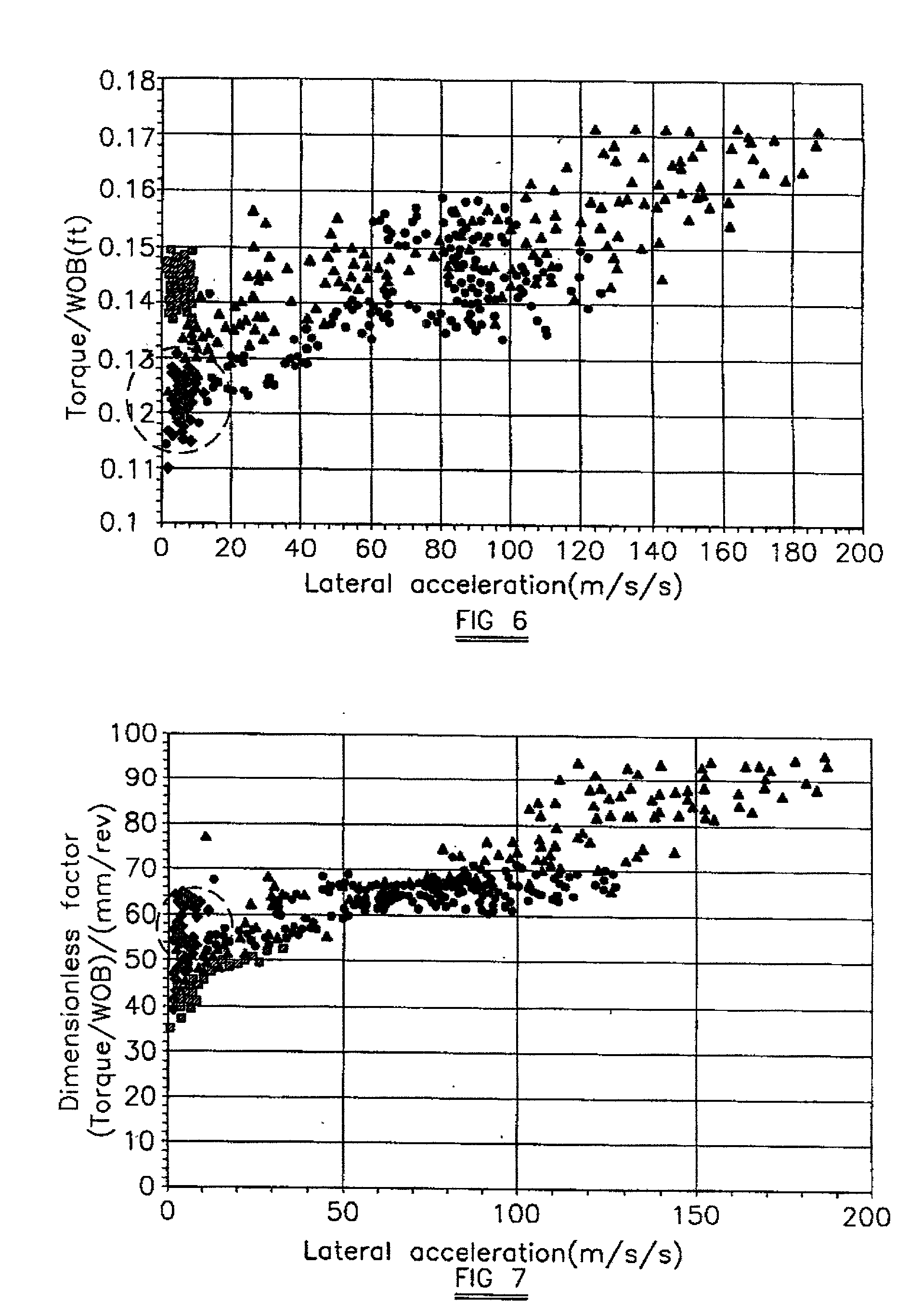
[0047] FIGS. 6 and 7 show the correlation between lateral vibration and torque in Bit B. In FIG. 6 torque / weight-on-bit, in feet, is plotted against lateral acceleration, in m / s / s, and...


PUM


Abstract

The invention provides a rotary drag-type drill bit in which the relationship of torque to rotary bit speed is such that torque generally increases with bit speed. Such a bit has a reduced tendency to exhibit the phenomenon known as "stick-slip" while drilling, when compared with bits having a different torque /speed characteristic, as a result of the positive damping effect of the torque/speed relationship. One method of designing such a drill bit comprises ascertaining the torque/rotary bit speed relationship, or other correlated relationships, for a number of different drill bit designs and then selecting from those designs a design having the desired type of relationship. Examples of drill bit structures specifically designed to achieve the desired torque/speed relationship are also disclosed.

Description

[0001] This is a continuation-in-part of U.S. patent application Ser. No. 09 / 210,518, filed Dec. 11, 1998, by Malcolm Taylor, et al., entitled "Rotary Drag-Type Drill Bits and Methods of Designing Such Bits" now pending.[0002] 1. Field of the Invention[0003] The invention relates to the design of rotary drag-type drill bits for use in drilling holes in subsurface formations.[0004] 2. Description of the Related Art[0005] As is well known, drag-type drill bits for boring earth formations comprise a bit body having a shank for connection to a drill string and a plurality of fixed cutters mounted on the bit body. A passage in the bit body supplies drilling fluid to nozzles in the surface of the bit for cleaning and cooling the cutters. In one common form of bit, a bit body has a leading face which comprises a number of circumferentially spaced blades extending outwardly away from the central axis of rotation of the bit, cutters being mounted along each blade. In polycrystalline diamond ...

Claims


Application Information

Patent Timeline
IPC IPC(8): E21B10/42
CPCE21B10/42E21B10/43
Inventor TAYLOR, MALCOLMMURDOCK, ANDREWJELLEY, DAVID
Owner CAMCO INT
Why Eureka
Try Eureka