Electromagnetic induction device

a technology of induction device and electromagnetic field, which is applied in the direction of transformer/inductance magnetic core, fixed transformer, coil arrangement, etc., can solve the problems of increasing the type of core pieces and, hence, the manufacturing cost, and the inability to compactly assembly the known transformer 64 discussed abov

Inactive Publication Date: 2001-09-27
TABUCHI ELECTRIC CO LTD +1
View PDF0 Cites 16 Cited by
  • Summary
  • Abstract
  • Description
  • Claims
  • Application Information

AI Technical Summary

Problems solved by technology

It has, however, been found that the known transformer 64 discussed above has a problem.
As such, the transformer 64 of the structure discussed above is incapable of being assembled compact and requires a relatively large space for mounting on a circuit substrate.
Accordingly, the known transformer 64 requires two types of core pieces of different sizes and this leads to increase of the type of core pieces and, hence, that of the manufacturing cost.
For these reasons, a circuit unit including the transformer 64 mounted on the circuit substrate requires a relatively large space for installation and, therefore, application thereof is limited, thereby constituting a cause of the high frequency heating apparatus incapable of being manufactured compact.

Method used


Image

  • Electromagnetic induction device
  • Electromagnetic induction device
  • Electromagnetic induction device

Examples


first embodiment

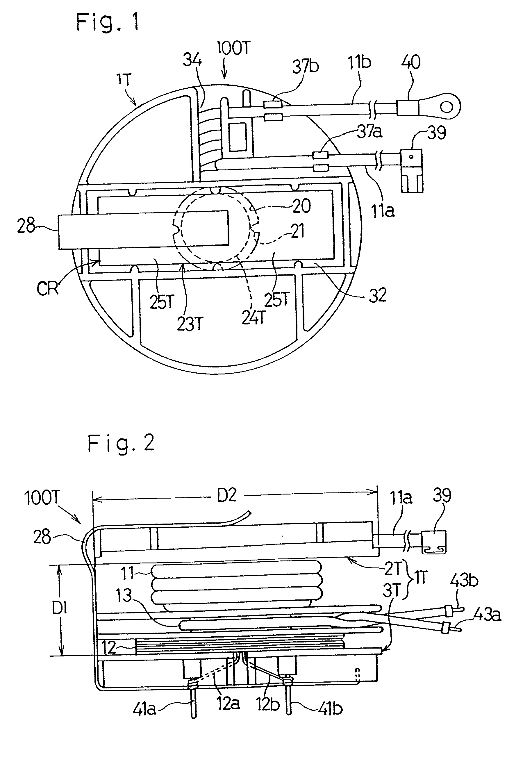
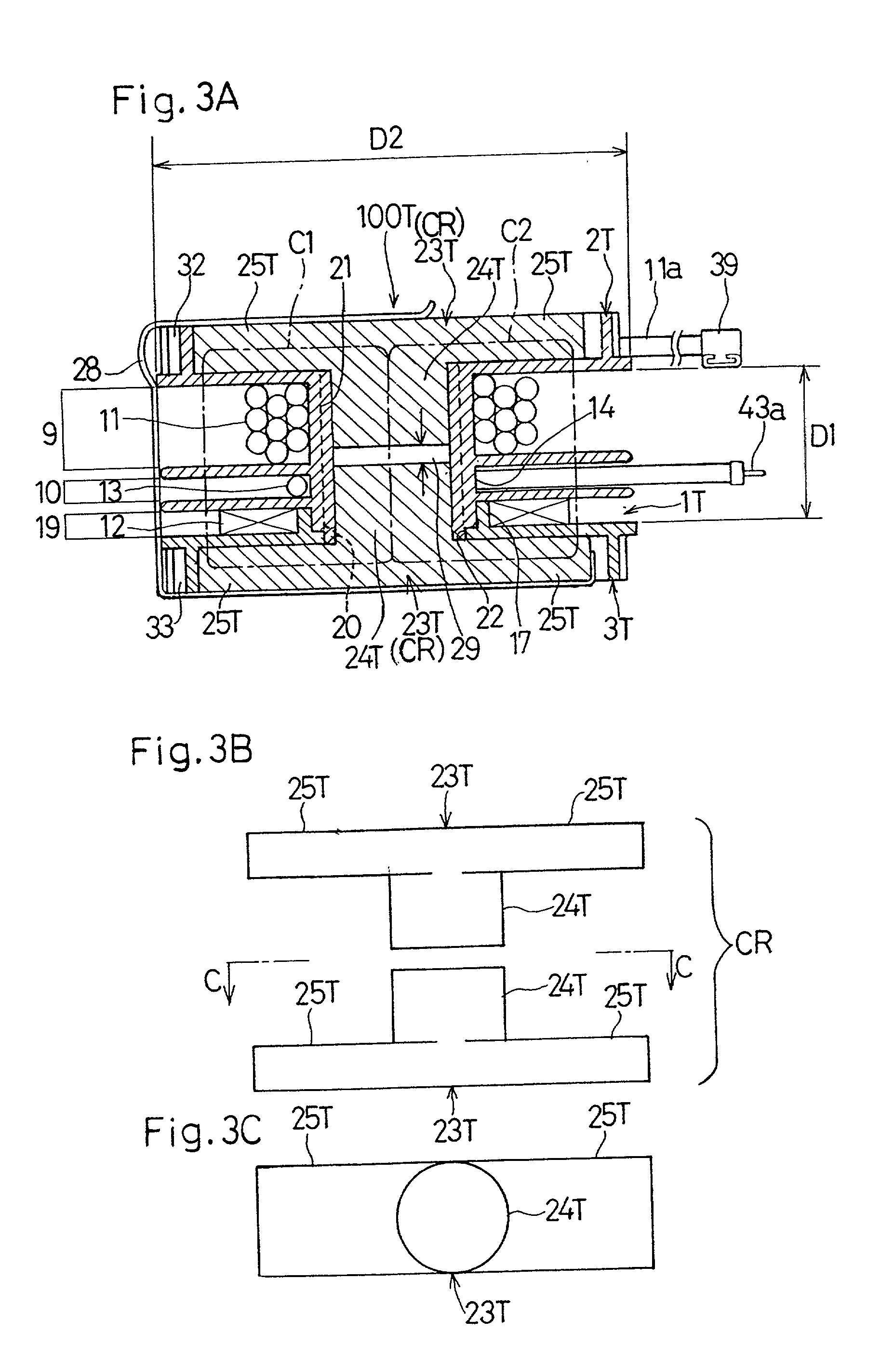
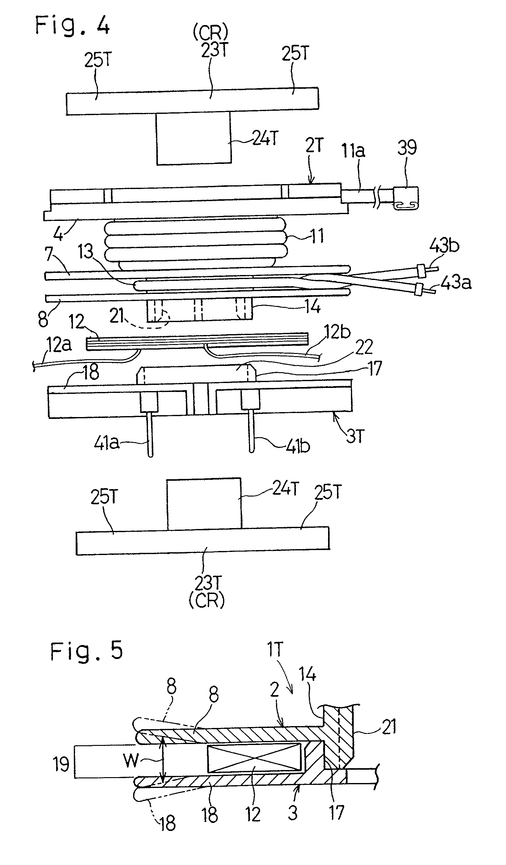
[0065] Referring first to FIGS. 1 to 3, there is shown a transformer 100T according to the present invention. The transformer 100T is a sort of electromagnetic induction devices for driving a magnetron employed in a high frequency heating apparatus generally such as, for example, an electronic oven. The transformer 100T includes a bobbin 1T made of a synthetic resin having an electric insulating property and is, as shown in FIG. 4, made up of axially separated first and second bobbin pieces 2T and 3T. The first bobbin piece 2T includes a hollow cylindrical body 14 having its outer peripheral surface formed integrally with first, second and third annular collars 4, 7 and 8 that lie parallel to each other. This first bobbin piece 2T has a primary winding frame 9 in the form of a primary winding groove bound by a portion of the hollow cylindrical body 14 and the first and second annular collars 4 and 7, and a heater winding frame 10 in the form of a heater winding groove bound by anoth...

third embodiment

[0098] The secondary circuit substrate 43 is, as is the case with the previously described third embodiment, fitted to and carried by the substrate mount 50 with its bottom resting on support projections (not shown) formed integrally with a bottom surface of the substrate mount 50, while catch pawl 53 at respective free ends of ribs 52 formed on the bottom surface of the substrate mount 50 so as to protrude upwardly therefrom as shown in FIG. 12 are engaged to associated side edges of a mounting surface of the secondary circuit substrate 43 to retain the latter in position. Also, the heater winding 13 is formed by winding a heating wire in a single turn around and within the heater winding frame 10 shown in FIG. 15 and has its opposite ends defining respective lead lines 13a and 13b. The lead line 13a of the heater winding 13 is electrically connected directly with the magnetron through a tab terminal member 51 whereas the other lead line 13b is, after having been drawn outwardly an...

second embodiment

[0102] As shown in FIG. 14, the first and second core pieces 23L and 23L are inserted respectively into the throughholes 20 and 22 in the first and second bobbin pieces 2L and 3L forming the bobbin 1L of the same shape as that in the previously described The substrate mount 42 is formed integrally with the second bobbin piece 3L and is positioned laterally of the bobbin 1L and radially outwardly of the windings 11 and 12. As shown in FIG. 15, respective free ends of the core arms 25L and 25L of the first and second core pieces 23L and 23L are positioned radially outwardly of the outermost perimeter of each of the windings 11 to 13. Even this transformer 500L is so designed that the coupling coefficient between the primary and secondary windings 11 and 12 can have a value within the range of 0.6 to 0.8.

[0103] Even in this fifth embodiment, the first and second core pieces 23L and 23L are of the same shape and dimensions, but they may have different shapes and dimensions and, in part...


PUM

PropertyMeasurementUnit
frequencyaaaaaaaaaa
axial widthaaaaaaaaaa
radial sizeaaaaaaaaaa

Abstract

An electromagnetic induction device having a flat configuration that requires a relatively small space for installation on a circuit substrate includes a flat bobbin (1T) having a length (D1) smaller than a radial size (D2) thereof has primary and secondary windings (11, 12) wound thereon. This bobbin (1T) has coaxially aligned throughholes (20, 22) defined therein into which core legs (24T and 24T) of generally T-shaped first and second core pieces (23T, 23T) are inserted from opposite directions, respectively. Respective core arms (25T, 25T) of the first and second core pieces (23T, 23T) extend parallel to each other.

Description

[0001] 1. Field of the Invention[0002] The present invention relates to an electromagnetic induction device such as, for example, a transformer utilizing an inverter and, more particularly, to the electromagnetic induction device of a type finding a principal application in, for example, driving a magnetron.[0003] 2. Description of the Prior Art[0004] FIG. 27 illustrates an inverter-equipped high frequency heating apparatus such as, for example, an electronic oven, of a type disclosed in the Japanese Examined Patent Publication No. 7-40465. This known high frequency heating apparatus includes a rectifying circuit 62 for rectifying and smoothing an electric power from a commercial power source 61, an inverter 63 for converting the rectified and smoothed electric power into a high frequency alternating current of a frequency equal to or higher than 20 kHz, and a transformer 64 including a gapped core and having a primary winding 64p to which the high frequency alternating current is s...

Claims


Application Information

Patent Timeline
Patent Type & Authority Applications(United States)
IPC IPC(8): H01F27/30H01F30/10H05B6/36
CPCH01F27/306H01F30/10H05B6/36
Inventor MIYAZAKI, SINOBUYAMAGATA, FUMIAKISOUMA, HIDEAKIMASUDA, SHINICHITAKASHIGE, YUTAKAKAMBARA, SEIJI
Owner TABUCHI ELECTRIC CO LTD
Why Eureka
Try Eureka