Attachment method for piezoelectric elements

a piezoelectric element and piezoelectric technology, applied in the field of piezoelectric element attachment method, can solve the problems of high activity quotient, prior art has not provided an orifice plate-based continuous-action dispenser, and can not be easily portable, battery-operated, and convenient refilling. , the effect of convenient refilling and convenient portability

Inactive Publication Date: 2001-11-22
SC JOHNSON & SON INC
View PDF0 Cites 28 Cited by
  • Summary
  • Abstract
  • Description
  • Claims
  • Application Information

AI Technical Summary

Benefits of technology

0009] It is an object of the present invention to provide a highly efficient, consistent, and reliable dispenser for liquid active materials, employing an orifice plate securely joined with a ceramic piezoelectric element. While the invention is described as comprising a ceramic piezoelectric element, it is understood that the invention is not limited thereto, but also extends to other piezoelectric materials having the requisite properties for use, and resistance to the elevated temperatures which accompany joining elements by soldering. By liquid

Problems solved by technology

Such atomizers and/or dispensers fail to provide a system by which liquid to be dispersed is supplied to the vibratory mechanism/surface without resulting in corrosion, solvent activity by the active liquid, or bond failure at the point of joining of the piezoelectric element and the orifice plate, particularly when the active liquids are such as perfume

Method used


Image

  • Attachment method for piezoelectric elements
  • Attachment method for piezoelectric elements
  • Attachment method for piezoelectric elements

Examples


Embodiment Construction

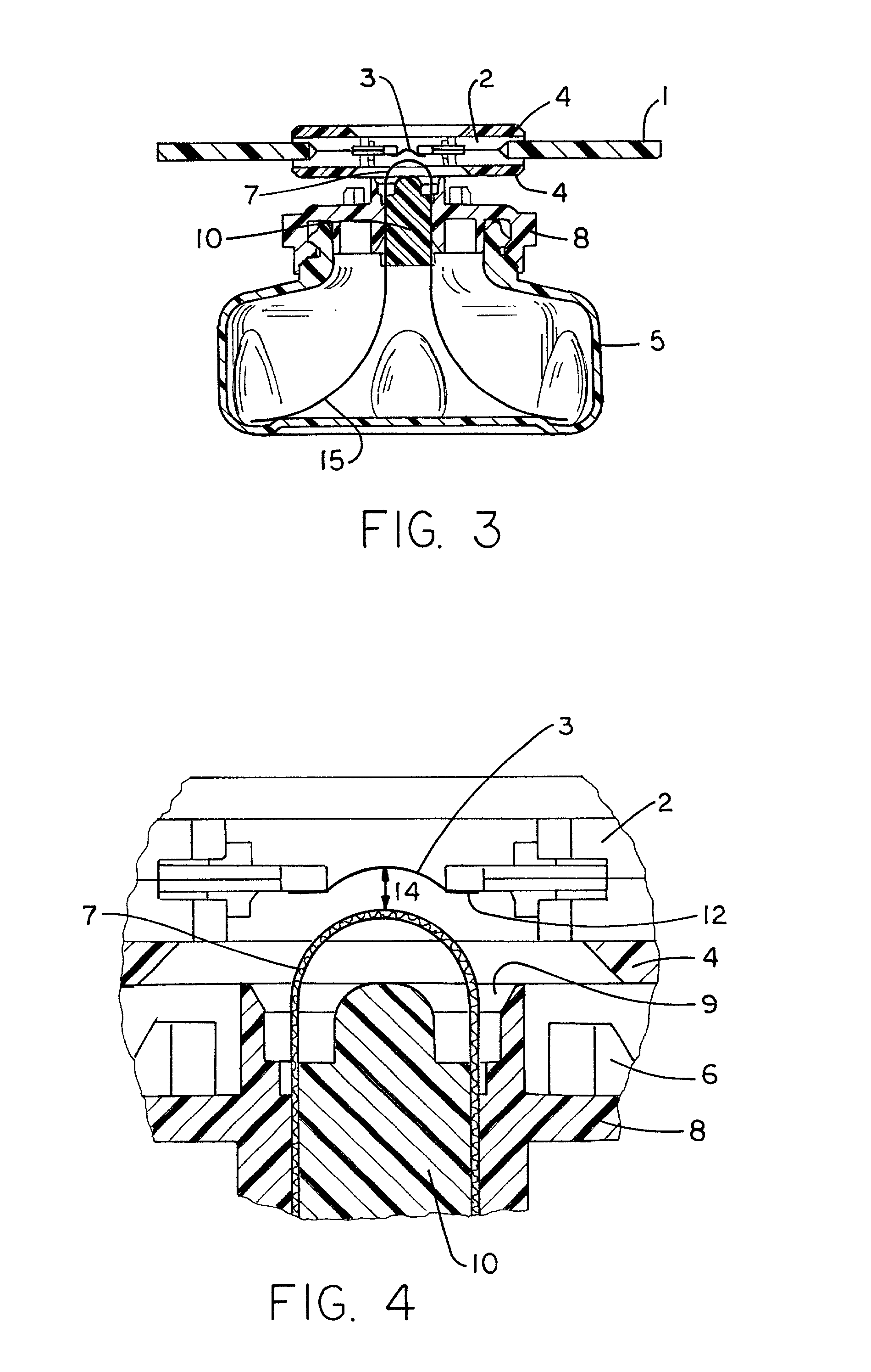
[0024] While FIGS. 1 through 6 are more specifically directed to a preferred embodiment of the invention, FIGS. 7 and 8 are more generally directed to the full scope of the present invention, which envisions joining of the piezoelectric element to the orifice plate in a manner which is in contrast to the conventional practice of those of ordinary skill in the art.

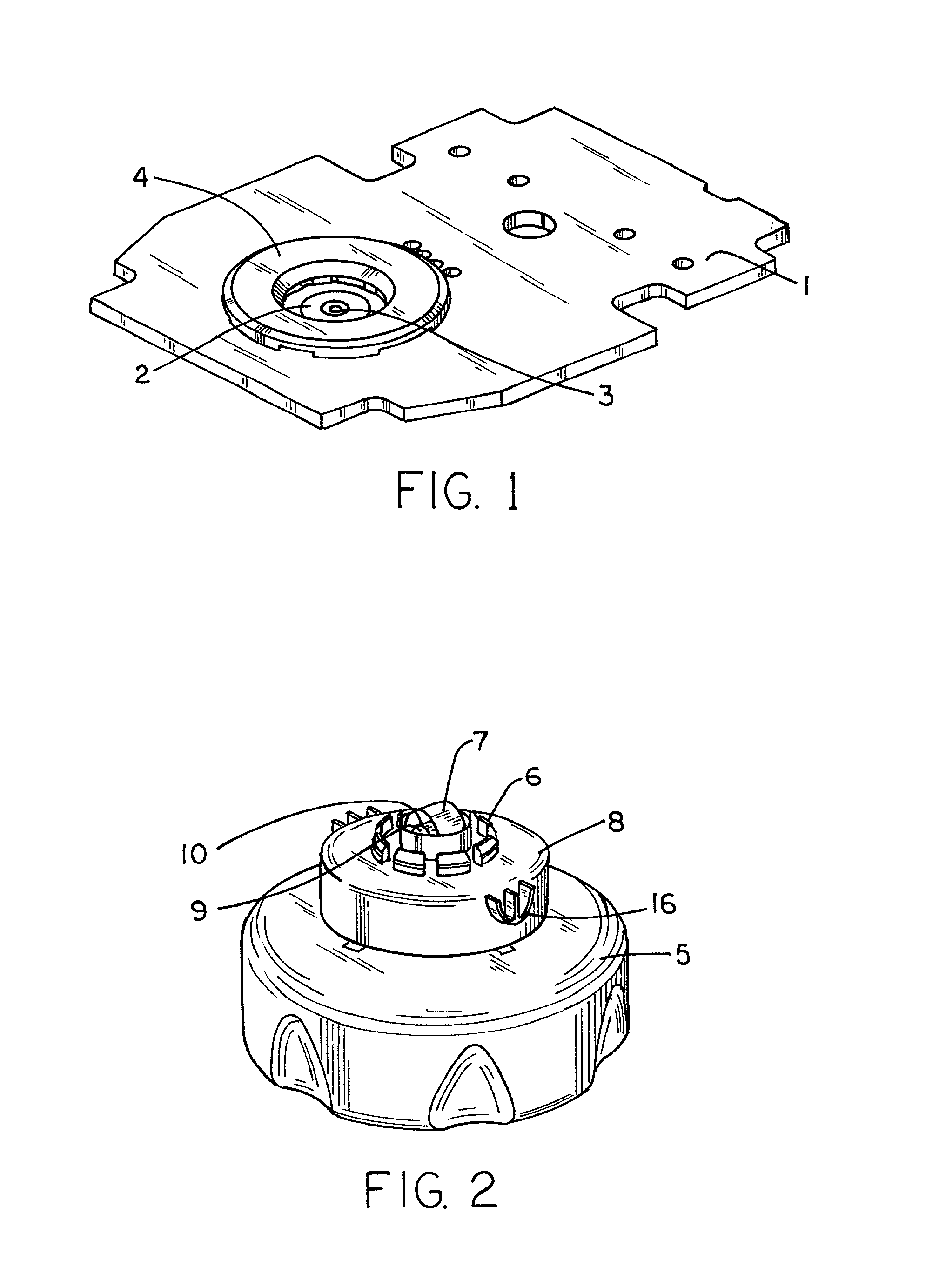
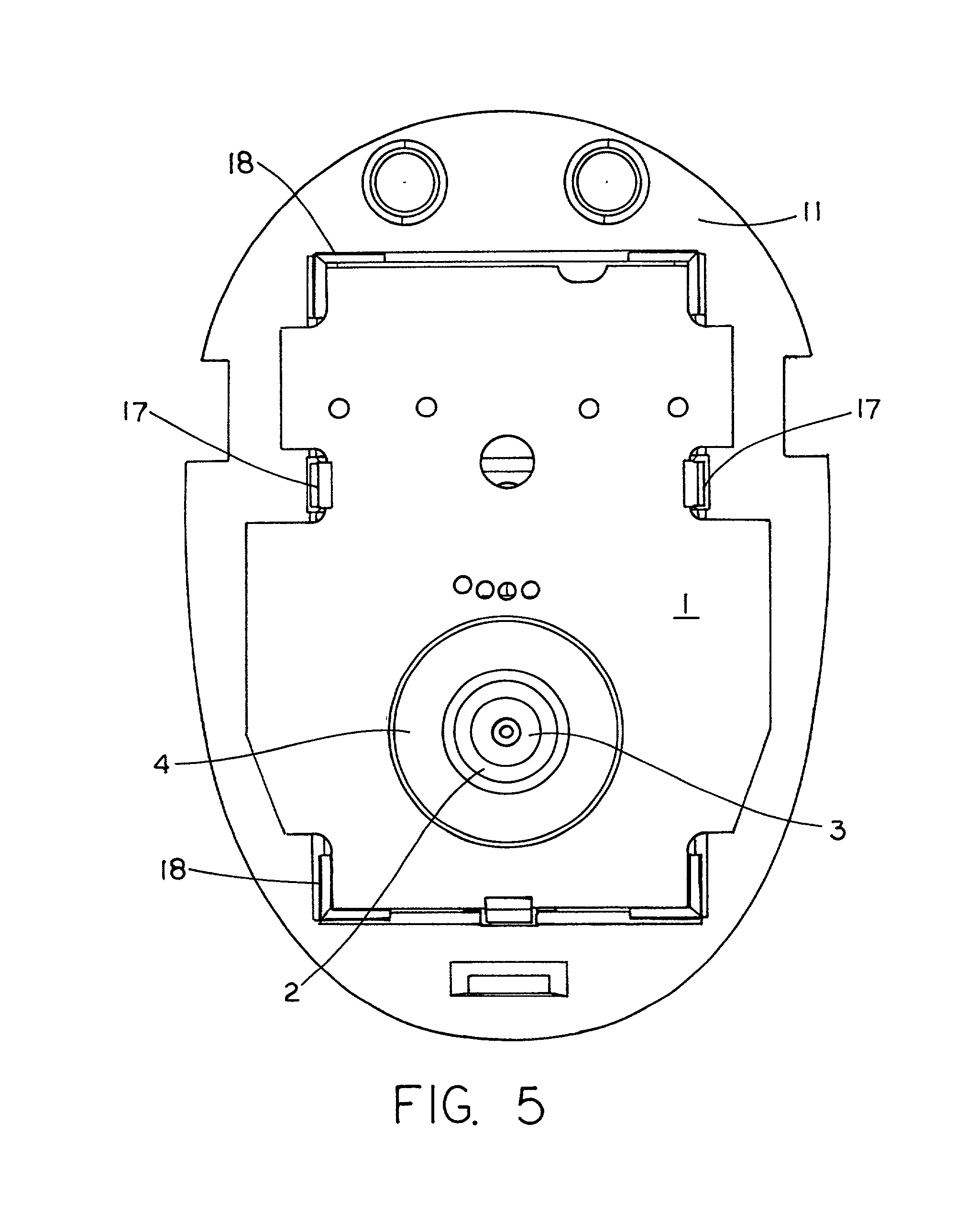
[0025] FIG. 1 illustrates the general relationship between a printed circuit board, 1, in which the piezoelectric element 2 is located. The circuit board, 1, is illustrated without the electronic circuitry and battery associated therewith for clarity and ease of understanding of the present invention. It is also to be understood that the circuit board is, in use, attached to the chassis of a dispenser, which chassis is in turn placed in a decorative shell-like housing or receptacle (not shown) for use. The chassis board 11 is shown in top view in FIG. 5, while the housing is not illustrated. The decorative receptacle or hou...


PUM


Abstract

Disclosed herein is a piezoelectric liquid delivery system or atomizer for production of droplets of liquid or liquid suspensions by means of a battery operated atomizer utilizing an orifice plate in communication with a ceramic piezoelectric element. By use of solder joining to bond the orifice plate to the piezoelectric element, and subsequent repolarization of the piezoelectric element if necessary, superior results are achieved.

Description

PRIORITY[0001] This application claims the benefit of U.S. Provisional Application No. 60 / 123,208, filed Mar. 8, 1999.[0002] The present invention relates, broadly, to the field of atomization of liquids for dispersal in the form of aerosols. More specifically, the invention relates to means for the distribution of a liquid active material, such as a perfume, air freshener, insecticide formulation, or other material, in the form of fine particles or droplets, as in a fine spray, by means of a piezoelectric device. In particular, the invention is directed to a piezoelectric liquid delivery system for the production of droplets of liquid, or liquid suspensions, by means of an electomechanical or electroacoustical actuator. More specifically, the present invention relates to a battery operated piezoelectric dispenser utilizing an orifice plate in communication with a piezoelectric element. It has been found that by joining the orifice plate to the vibrating piezoelectric element by a s...

Claims


Application Information

Patent Timeline
IPC IPC(8): A61L9/14B05B17/00B05B17/06
CPCA01M1/205A61L9/14B05B17/0646B05B17/0684B05B17/06
Inventor TOMKINS, DAVID A.CLARK, GEORGE A.NAVIN, ERIC R.MARTENS, EDWARD J. III
Owner SC JOHNSON & SON INC
Why Eureka
Try Eureka