

Optical fiber
a technology of optical fiber and fiber, applied in the field of optical fiber, can solve the problems of optical fiber suffering, optical fiber losing its effective core area, and the assumption that the structure having refractive index distribution can be replaced by uniform mediums,
Image

Examples
first embodiment
[0066] In this manner, the optical fiber of the first embodiment can obtain the large negative chromatic dispersion. Accordingly, at the time of compensating for the dispersion of other optical fiber having the positive dispersion, the length of the optical fiber can be shortened. Further, simultaneous with the achieving of the large negative chromatic dispersion and the large negative chromatic dispersion slope, the effective core area can be increased. Accordingly, the nonlinear optical phenomena can be suppressed whereby the transmission quality can be enhanced.
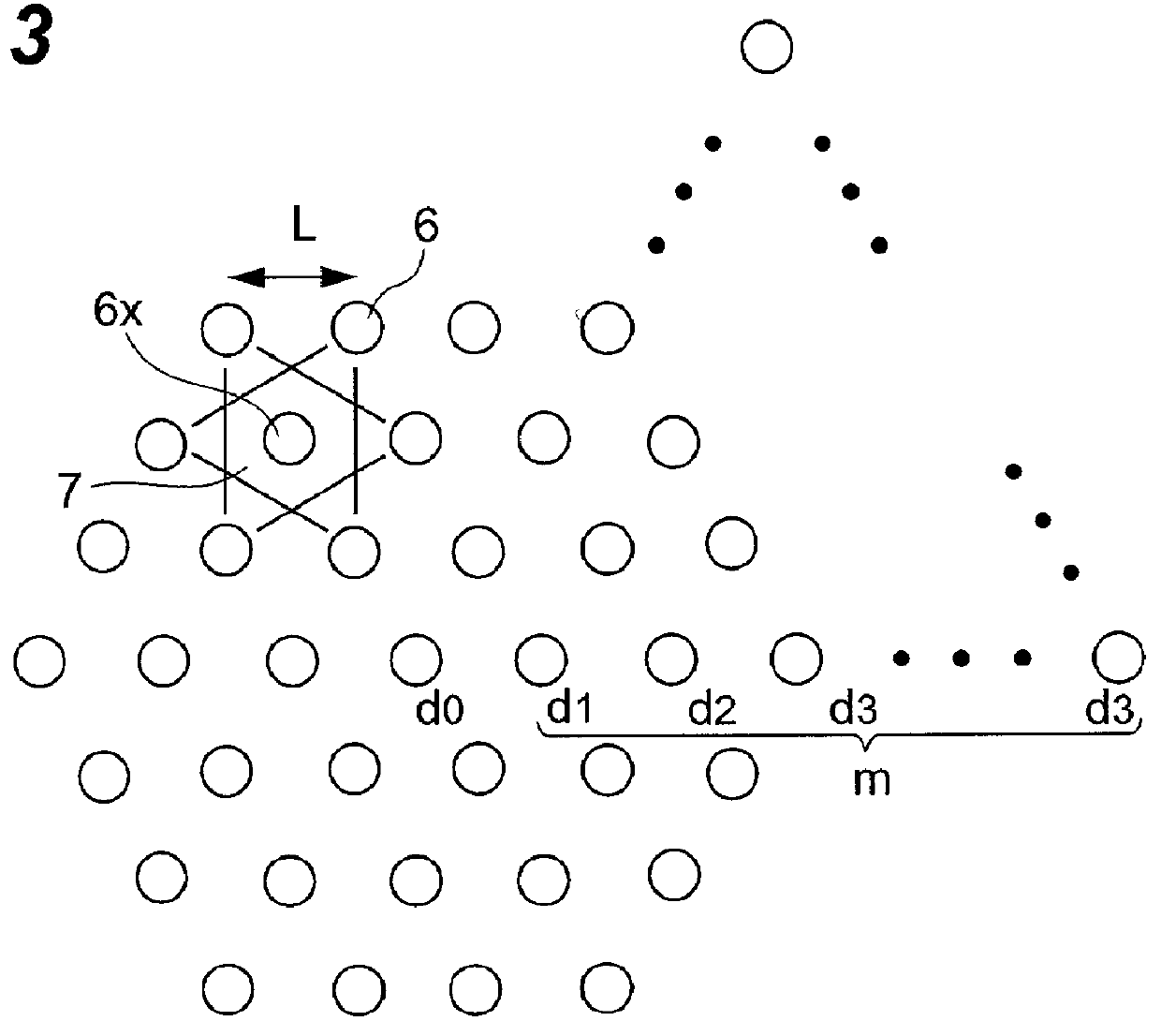
[0067] FIG. 9 is a view showing the calculated result of the respective structural chromatic dispersions and the effective core areas at the example 1 and the comparison examples 1, 2 when the pitches are changed (a suffix a being added to classify this case from the case shown in FIG. 8 hereinafter) in a comparison form. Here, the pitches L are set such that the effective core areas A.sub.eff of respective optical fibers ...
second embodiment
[0074] In this manner, since the optical fiber has the large effective core area, the occurrence of the nonlinear optical phenomena can be suppressed whereby the transmission quality can be enhanced.
[0075] FIG. 13 is a view which shows the calculated result of the effective core area when the respective pitches L of the examples 2, 3 and the comparison example 2 are changed in a comparison form. Here, the pitches L are set such that the effective core area A.sub.eff at the wavelength of 1550 nm becomes 12 .mu.m.sup.2in all of the examples 2, 3 and the comparison example 2. That is, the pitch values are respectively set to 1.33 .mu.m in the example 2, 1.53 .mu.m in the example 3 and 1.21 .mu.m in the comparison example 2.
[0076] Focusing on the change of the effective core area A.sub.eff at the wavelength .lambda.=1550 nm, with respect to the magnitude of the change of the effective core area A.sub.eff relative to the change of the wavelength, the example 2 has the smaller magnitude ...
third embodiment
[0091] Accordingly, the optical fiber of the third embodiment can reduce the sensitivity of the structural chromatic dispersion to the shape of the voids. Further, with the introduction of the voids, the bending loss can be reduced. In general, when the chromatic dispersion is displaced from a given value, the deterioration of the transmission quality caused by the residual dispersion in the transmission path occurs and hence, the high fabrication accuracy is required with respect to the chromatic dispersion. On the other hand, the bending loss is only required to be lower than a given threshold value, no high fabrication accuracy is required with respect to the bending loss. In the optical fiber of this embodiment, although the bending loss depends on the shape of voids, the chromatic dispersion does not depend on the shape of voids and hence, the demand for the fabrication technique with respect to the accuracy of the shape of voids can be alleviated.
[0092] In any one of examples ...
PUM
 Abstract
Description
Claims
Application Information
- IPC
- G02B6/02
- CPC
- G02B6/02028; G02B6/02261; G02B6/0228; G02B6/02347; G02B6/02352; G02B6/02357; G02B6/02361; G02B6/02366
- Inventors
- HASEGAWA, TAKEMI; SASAOKA, EISUKE