
X-ray mask structure, and x-ray exposure method and apparatus using the same

a mask and structure technology, applied in the field of x-ray mask structure and x-ray exposure method and apparatus, can solve the problems of low strength, inability to clean the x-ray mask structure, and remaining dust that cannot be removed

Inactive Publication Date: 2002-02-14
CANON KK
View PDF0 Cites 11 Cited by
  • Summary
  • Abstract
  • Description
  • Claims
  • Application Information

AI Technical Summary

Problems solved by technology

However, because of high aspect of the X-ray absorptive member of the X-ray mask structure, cleaning the X-ray mask structure is very difficult to accomplish.
There may remain dust not removed by the cleaning.
Further, since the supporting film for supporting the X-ray absorptive member is thin, its strength is low.
However, it requires a very complicated process to discriminate dust and a patter of high aspect.
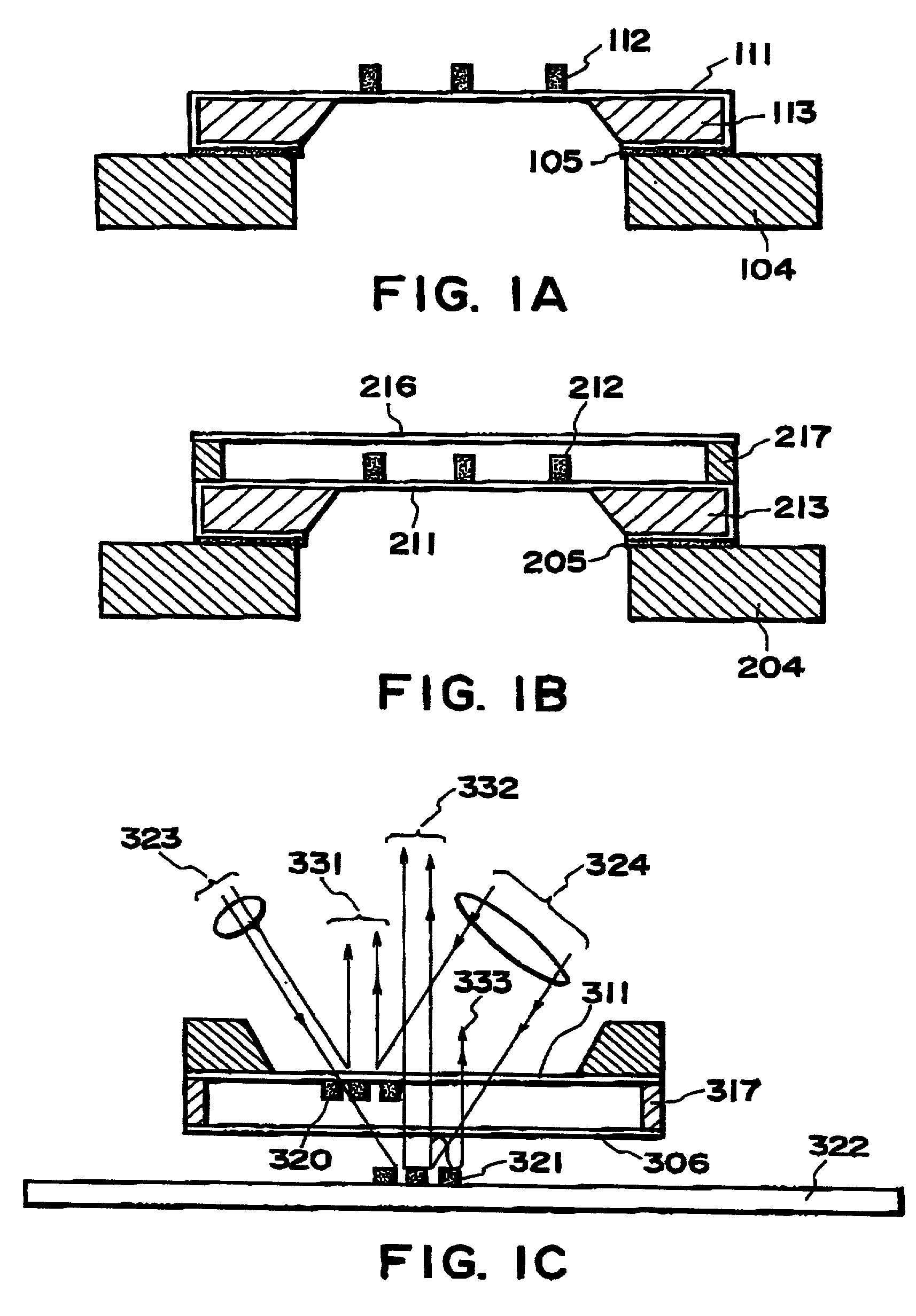
When an X-ray mask structure With a pellicle is used in an exposure process (Japanese Laid-Open Patent Application, Laid-Open No. 72119 / 1989), there may be a problem in relation to alignment of the X-ray mask structure with the X-ray exposure apparatus or to alignment of a wafer to be exposed through the X-ray mask structure.
Because of this, it may become difficult to accurately detect relative positional deviation of the X-ray mask structure and the wafer 322.
This causes adverse influence to detection of positional deviation.
Also, the intensity of alignment light passing through the pellicle of the X-ray mask structure may he reduced it, and a sufficient signal level for keeping the precision for positional deviation detection may not be maintained
This problem many apply to other alignment methods.
In a method where a mask and a wafer are provided with grating lenses and deflection angle of diffraction light by the grating lenses is measured, or in a method where images of marks of a mask and a water are detected, similarly, reflection of alignment light at a pellicle may produce noise light or a ghost image, causing lower alignment detection precision.

Method used


Image

  • X-ray mask structure, and x-ray exposure method and apparatus using the same
  • X-ray mask structure, and x-ray exposure method and apparatus using the same
  • X-ray mask structure, and x-ray exposure method and apparatus using the same

Examples


first embodiment

[0034] [First Embodiment]

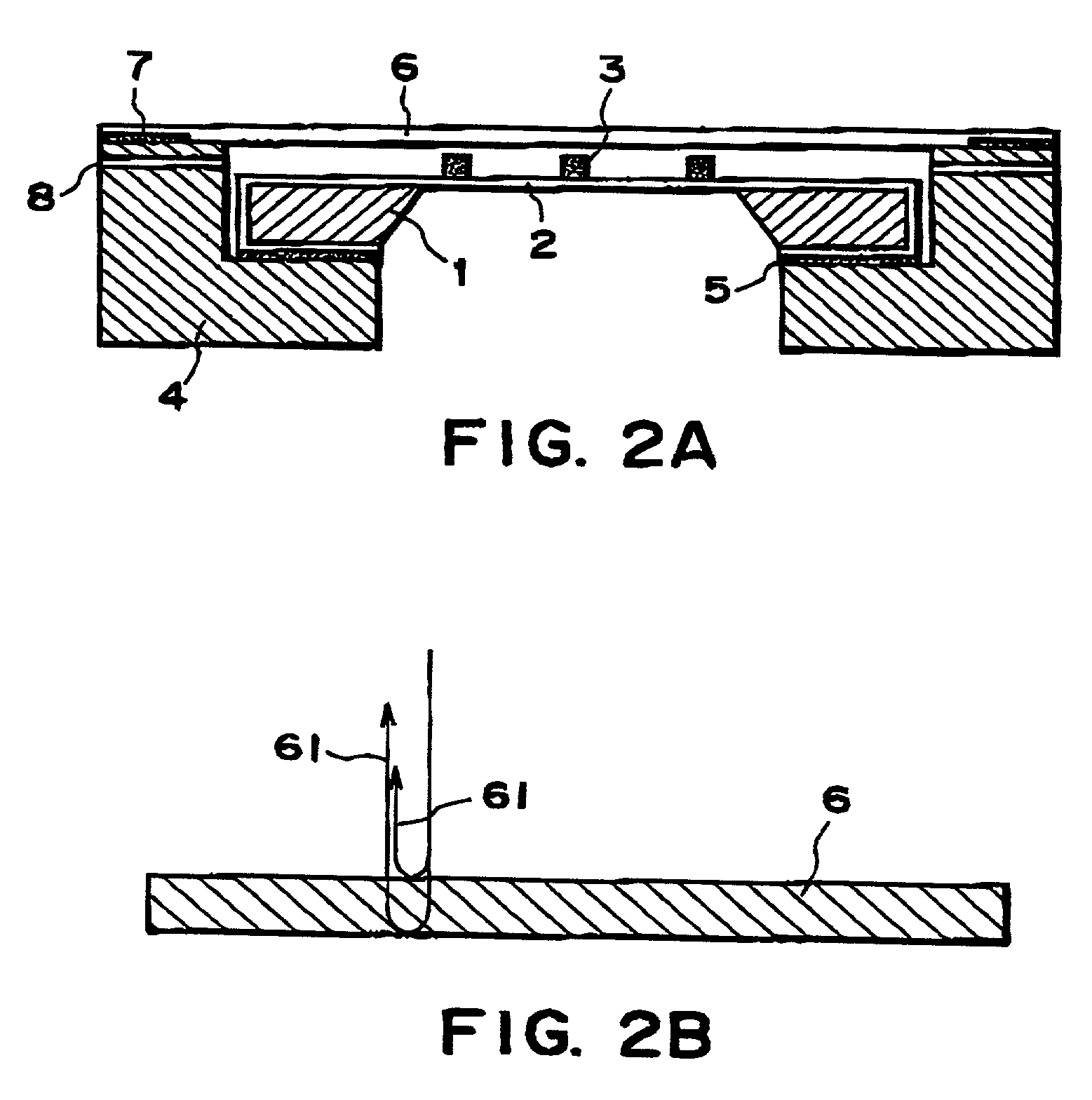
[0035] FIG. 2A it a sectional view of an X-ray mask Structure according to a first embodiment of the present invention. In the X-ray mask structure of this embodiment, as shown in FIG. 2A, an X-ray absorptive material 3 is formed in accordance with a pattern to be printed, ad a supporting film (X-ray transmission film) 2 in held by a holding frame 1 so that it is opposed to a workpiece, to be exposed, placed in the exposure apparatus. The holding frame 1 is made of Si of a thickness 2 mm. The supporting film 2 has X-ray transmissivity, and it comprises a SiC film of thickness 2.0 micron, formed by CVD process. The X-ray absorptive member 3 in formed by plating, the material thereof is Au. The holding frame 1 is fixed to a reinforcing member 4 by an adhesive agent 5. The reinforcing member is made of SiC

[0036] At the top face of the reinforcing member 4, that is, at the surface to be opposed to a workpiece in exposure process, there is a thin film (pellicle) ...

second embodiment

[0092] [Second Embodiment]

[0093] FIG. 13 is a schematic view for explaining an X-ray mask structure according to a second embodiment of the present invention. In the first embodiment, the thin film (dust protection film) having anti-reflection function to alignment light is made of a single material. In the second embodiment, on the other hand, the thin film (duet protection film) is made of plural materials in layers. FIG. 13 shows the sectional structure of a thin film (dust protection film) which is one of the components of an X-ray mask structure according to this embodiment. Disposition of the dust protection film in the X-ray mask structure of this embodiment, as well as the other components are similar to those shown in FIG. 2A, 5, 6 or 7 of the first embodiment.

[0094] As shown in FIG. 13, a thin film 56 having anti-reflection function to alignment light has a structure that, on the surface of a first material film 57, a second material film 59 is formed, and that, at the bot...

third embodiment

[0110] [Third Embodiment]

[0111] Referring to FIG. 8, a third embodiment of the present invention will be described in relation to an X-ray exposure method which uses an X-ray mask structure of the first or second embodiment. In the X-ray exposure method of this embodiment, an X-ray exposure apparatus such as described with reference to FIG. 8 may be used for production of microdevices such as semiconductor device, thin film magnetic head, or micro-machine, for example.

[0112] Except for use of an X-ray mask structure according to the first or second embodiment, the X-ray exposure method or exposure apparatus of this embodiment is based on any known method and apparatus.

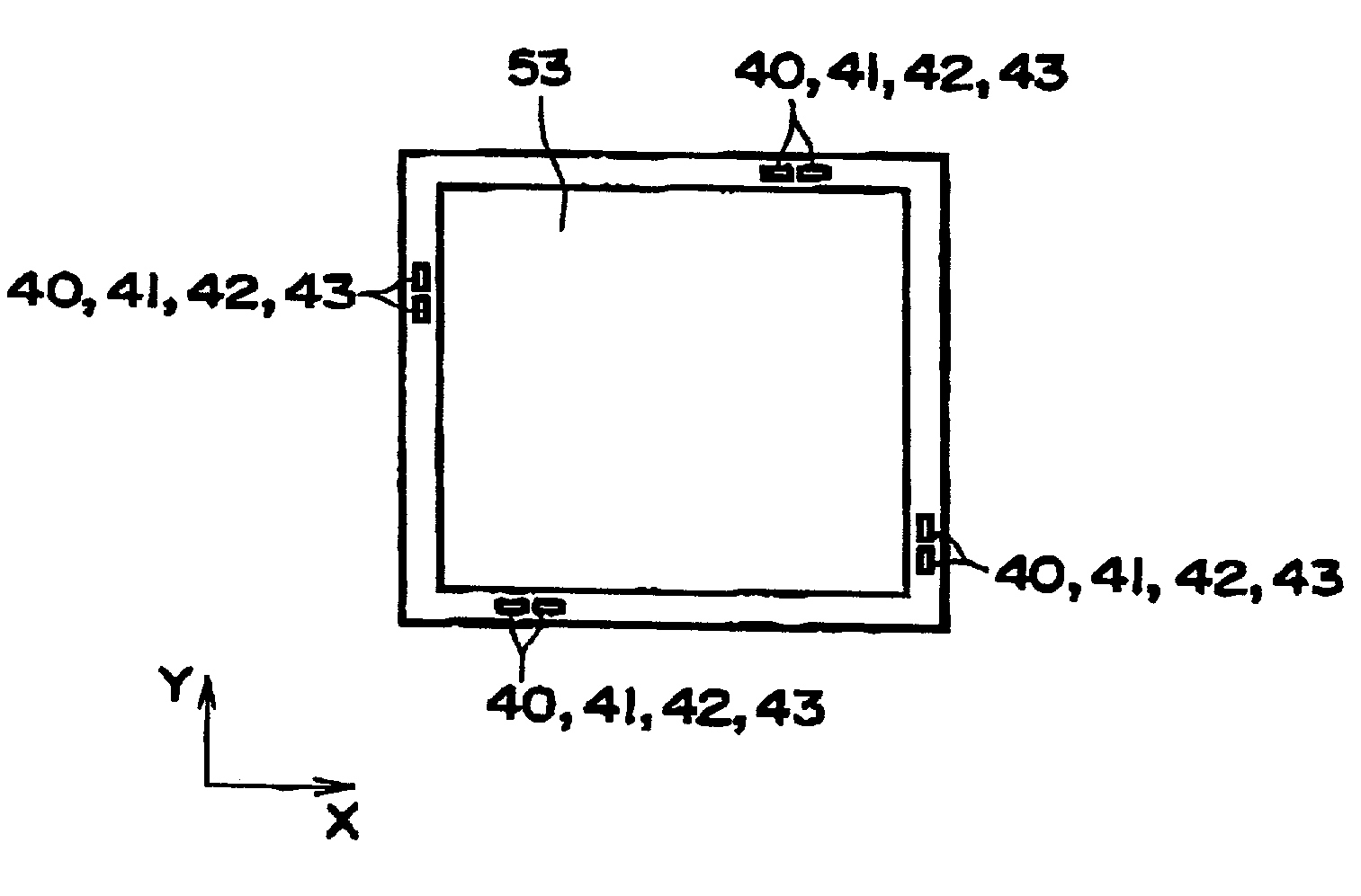
[0113] The X-ray exposure apparatus of FIG. 8 is used with a SOR ring (not shown) which is a synchrotron orbit radiation source. Synchrotron radiation light of sheet-beam shape emitted from the SOR ring has a sheet-like beam shape being expanded in lateral direction with uniform light intensity but having substantially...


PUM

PropertyMeasurementUnit
thicknessaaaaaaaaaa
thicknessaaaaaaaaaa
thicknessaaaaaaaaaa

Abstract

An X-ray mask structure for use in X-ray lithography includes an X-ray transmission film to be disposed opposed to a workpiece in X-ray exposure, the X-ray transmission film having an X-ray absorptive material corresponding to a pattern to be printed on the workpiece, and a thin film covering at least a portion of the X-ray transmission film, the thin film having an anti-reflection function with respect to alignment light to be projected to the thin film for direct or indirect detection of relative positional deviation between the mask structure and the workpiece.

Description

FIELD OF THE INVENTION AND RELATED ART[0001] This invention relates generally to an X-ray mask structure for use in X-ray lithography. The invention further relates to an X-ray exposure method and apparatus and a semiconductor device manufacturing method which use such am X-ray mask structure. The invention still further relates to a semiconductor device to be produced on the basis of the semiconductor device manufacturing method.[0002] In the stream of increase in density and speed of a semiconductor integrated circuit, reduction in linewidth of an integrated circuit pattern and improvement in device manufacturing method have been required. In order to meet this, steppers as X-ray exposure apparatus using exposure light of X-ray region (2-150 angstroms) have been developed,[0003] X-ray mask structures for such X-ray exposure apparatus are usually such as shown In FIG. 1A.[0004] FIG. 1A is a sectional view of a conventional X-ray mask structure As shown, the X-ray mask structure com...

Claims


Application Information

Patent Timeline
Patent Type & Authority Applications(United States)
IPC IPC(8): G03F1/22G03F7/20H01L21/027
CPCG03F1/22G03F1/62G03F1/64G03F7/70983
Inventor MATSUMOTO, TAKAHIROCHIBA, KEIKO
Owner CANON KK
Learn More