Simply interfaced semiconductor integrated circuit device including logic circuitry and embedded memory circuitry

a technology of integrated circuits and logic circuits, applied in the direction of memory adressing/allocation/relocation, digital transmission, instruments, etc., can solve the problems of general versatility, loss of connection to an ordinary microcomputer

Inactive Publication Date: 2002-04-04
RENESAS ELECTRONICS CORP
View PDF8 Cites 39 Cited by
  • Summary
  • Abstract
  • Description
  • Claims
  • Application Information

AI Technical Summary

Problems solved by technology

Hence, a general versatility such as to be connected to an ordinary microcomputer was lost, or specific commands were required in a microcomputer for controlling the system.

Method used


Image

  • Simply interfaced semiconductor integrated circuit device including logic circuitry and embedded memory circuitry
  • Simply interfaced semiconductor integrated circuit device including logic circuitry and embedded memory circuitry
  • Simply interfaced semiconductor integrated circuit device including logic circuitry and embedded memory circuitry

Examples


third example

[0323] [Third Example]

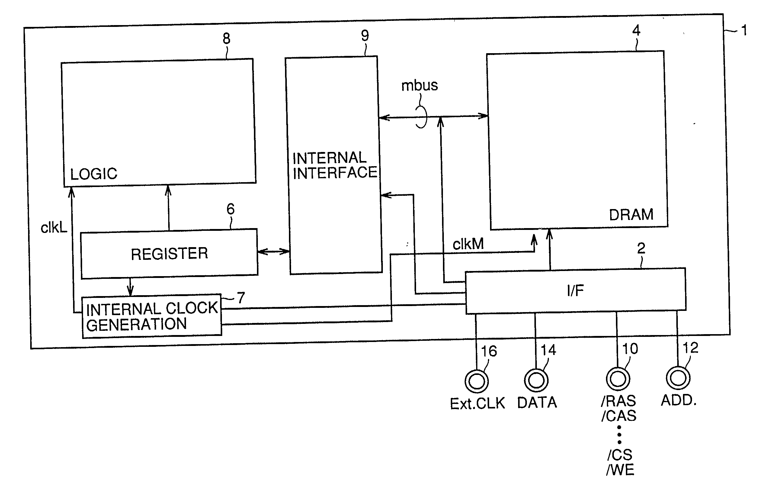
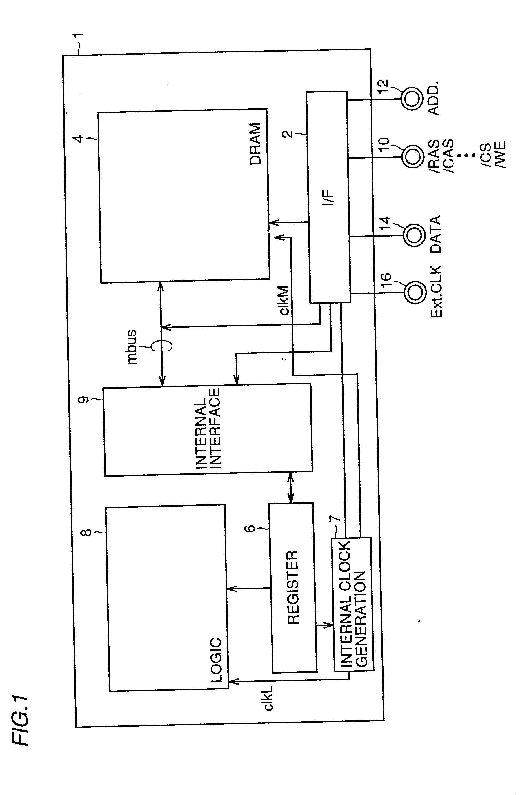
[0324] FIG. 38 a block diagram representing a configuration of a logic integrated DRAM 30 of a third example, obtained by modifying the configuration of the semiconductor integrated circuit device 1 of the first example.

[0325] Referring to FIG. 38, a logic integrated DRAM 30 includes: a SDRAM section 32; and a logic section 34.

[0326] The SDRAM section 32 includes: an interface section 36 receiving an external signal to output a control signal according to the external signal; and a DRAM core 38 performing data holding according to an output from the interface section 36. The interface section 36 includes: a control signal input circuit 40 receiving control signals / CS, / RAS, / CAS, / WE and DQM; a clock buffer 44 receiving a clock signal CLK and a clock enable signal CKE to generate an internal clock; an address buffer 46 catching an address signal A0 to An in synchronism with an output of the clock buffer 44; and an I / O circuit 52 performing input / output of data...

fourth embodiment

[0377] Fourth Embodiment

[0378] FIG. 45 is a schematic diagram for describing a configuration of a logic integrated DRAM 130 of a fourth example of the present invention.

[0379] A configuration of the logic integrated DRAM 130 of a fourth embodiment of the present invention shown in FIG. 45 is basically almost similar to that of the logic integrated DRAM 30 of the third example shown in FIG. 38.

[0380] However, first of all, in the logic integrated DRAM 130, 4 banks #0 to #3 are provided in a memory cell array 38 and the banks are so configured to be read out from or written to independently of each other.

[0381] Corresponding to such a configuration, row decoders 56.0 to 56.3, column decoders 58.0 to 58.3 and sense amplifiers 60.0 to 60.3 are provided to the respective banks.

[0382] Furthermore, in FIG. 45, a control signal input terminal 11 is newly provided to which terminal a control signal CRYPT for externally instructing a cryptographic operation is given.

[0383] Furthermore, in the...

fifth example

[0523] Fifth Example

[0524] FIG. 61 is a schematic block diagram for describing a configuration of a logic integrated DRAM 132 of a fifth example of the present invention.

[0525] A configuration of the logic integrated DRAM 132 of the fifth example shown in FIG. 61 is almost the same as of the logic integrated DRAM 130 of the fourth example shown in FIG. 45.

[0526] The logic integrated DRAM 132, however, is different from the logic integrated DRAM 130 of the fourth example in that the second register 86 is deleted and input / output of data on the logic circuit 74 is performed through the first register 84.

[0527] The other points are basically similar to corresponding points in configuration of the logic integrate DRAM 130 of the fourth example shown in FIG. 45; therefore the same symbols are attached to the same constituents and no description thereof is repeated.

[0528] [Register-Register Operation]

[0529] Next, description will be given of a register-register operation of the logic inte...


PUM


Abstract

An interface circuit performs supply / reception of data with a register instead of supply / reception of data with DRAM when an area specified by an address signal is a logic control area. Data signals in the case are a control command for a logic circuit held in a register and input data to be processed. The logic circuit takes charge of a critical path in processing time such as cryptographic processing and image processing. A processing result is held in the register. The register circuit switches between storage data stored in DRAM and data given from a terminal group to select data to be processed according to a control signal.

Description

[0001] 1. Field of the Invention[0002] The present invention relates to a semiconductor memory device, and particularly, to a semiconductor memory device having logic circuitry integrated therewith and a control method therefor.[0003] 2. Description of the Background Art[0004] FIG. 101 is a plan view representing a pin configuration of a 64 Mbit synchronous dynamic random access memory (SDRAM) with a 16 bit word configuration.[0005] FIG. 102 is a table representing terminal names of SDRAM and their functions.[0006] Referring to FIGS. 101 and 102, a prior art SDRAM is housed in, for example, a package with 54 pin terminals including a terminal CLK to which a master clock is inputted, a terminal CKE to which a clock enable signal is inputted, a terminal / CS to which a chip select signal is inputted, a terminal / RAS to which a row address strobe signal is inputted, a terminal / CAS to which a column address strobe signal is inputted and a terminal / WE to which a write enable signal is inpu...

Claims


Application Information

Patent Timeline
Patent Type & Authority Applications(United States)
IPC IPC(8): G06F12/00G11C11/401G06F12/02G11C7/10G11C7/22G11C11/406G11C11/407G11C11/4093G11C11/4096
CPCG11C7/1006G11C7/1072G11C2207/104G11C11/4093G11C11/4096G11C7/22G11C11/407
Inventor YAMAUCHI, TADAAKIKOZARU, KUNIHIKO
Owner RENESAS ELECTRONICS CORP
Why Eureka
Try Eureka