
Hydrogen supply device

a technology of water supply device and hydrogen supply material, which is applied in the direction of electrochemical generator, sustainable manufacturing/processing, lighting and heating apparatus, etc., can solve the problems of unreacted combustion gas containing harmful components due to incomplete combustion, insufficient and ineffective heat transfer to the reforming material

Inactive Publication Date: 2002-05-30
DENSO CORP
View PDF10 Cites 28 Cited by
  • Summary
  • Abstract
  • Description
  • Claims
  • Application Information

AI Technical Summary

Benefits of technology

[0013] Preferably, the gas compressor is located in a reformed gas supply path communicating between the reforming section and the hydrogen consumption device such as a fuel cell so that the pressure of the high temperature fluid passage is isobaric to or higher than the pressure of the low temperature fluid passage, resulting in preventing the fluid leakage from the clearance between the rotary thermal storage and the gas seals.
[0014] Further, it is preferable that pressure adjusting means, for example, a pressure control valve operative to alter a fluid flow passage area, are located at the low temperature fluid passage on an upstream side of the heat exchange section and / or at the high temperature fluid passage on a downstream side of the heat exchange section. ECU controls the operation of the pressure adjusting means upon receipt of signals of the pressure detecting sensors located in the low and / or high temperature fluid passages in a vicinity of the rotary thermal storage so that a pressure difference between the low and high temperature fluid conduits is easily adjusted.
[0015] Moreover, it is preferable that the reforming material is supplied from two different supply sections. One is a first reforming material supply section in which a first reforming material containing at least water (and air) is supplied to the low temperature fluid passage on an upstream side of the heat exchange section. The other one is a second reforming material supply section in which second reforming material (fuel) containing at least hydride compounds is supplied to the low temperature fluid passage on a downstream side of the heat exchange section and mixed with the first reforming material to form the reforming material. With this construction, the deposition of the reforming material on walls of the rotary thermal storage and the blockage of through-holes of the rotary thermal storage can be prevented.

Problems solved by technology

The conventional hydrogen supply device having the structure mentioned above has a drawback that the heat transmitted to the pre-heating and evaporation sections from the combustion section is indirectly transferred to the reforming material, resulting in insufficient heat transfer to the reforming material, and, further, the heat transfer to the reforming material is not effective since the pre-heating and evaporation sections are located far away from the combustion section.
Further, at a time of actuation of the conventional hydrogen supply device, unreacted combustion gas containing harmful components due to incomplete combustion is likely to be exhausted to the outside.

Method used


Image

  • Hydrogen supply device
  • Hydrogen supply device
  • Hydrogen supply device

Examples


first embodiment

[0049] (First embodiment)

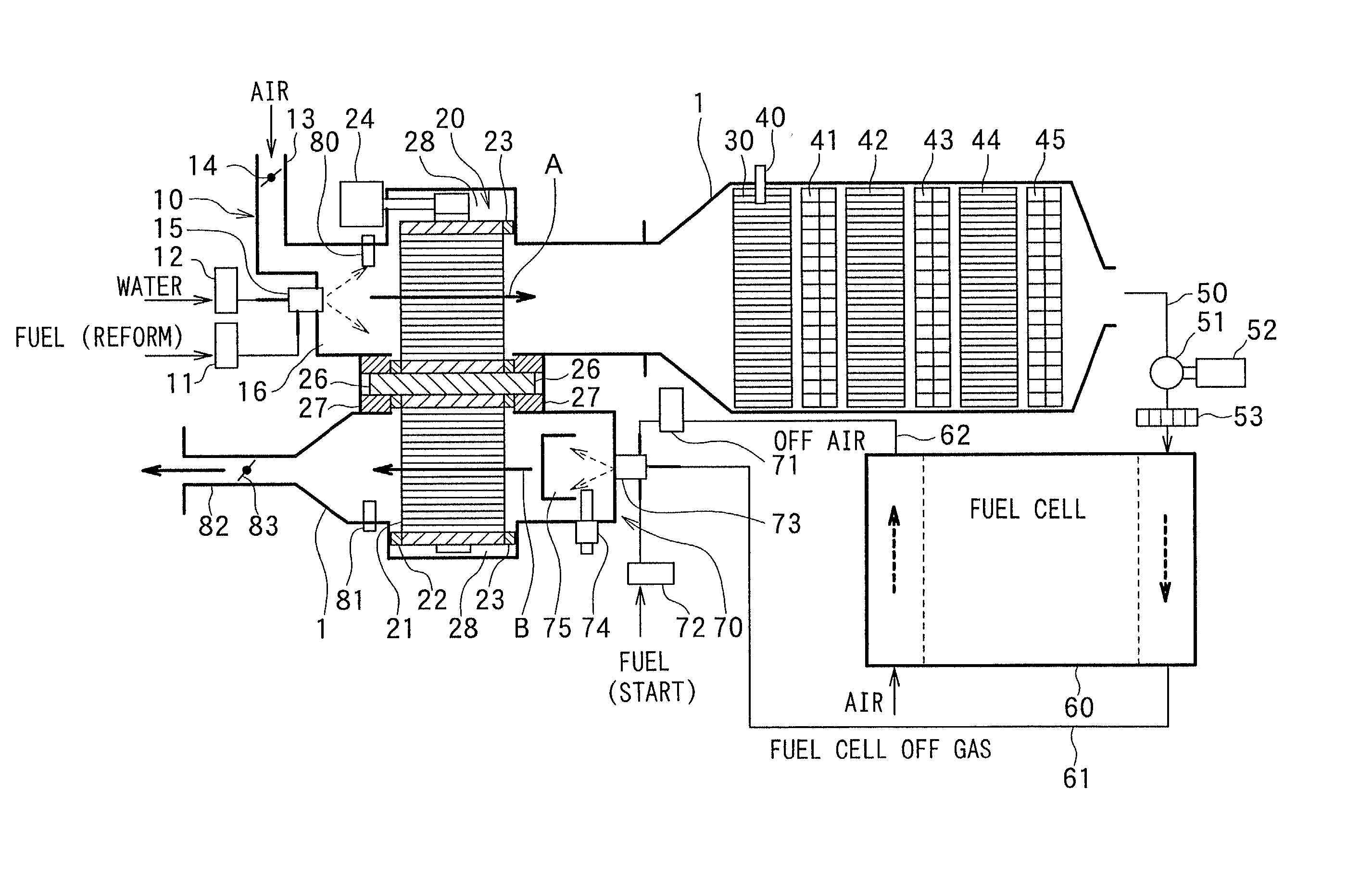
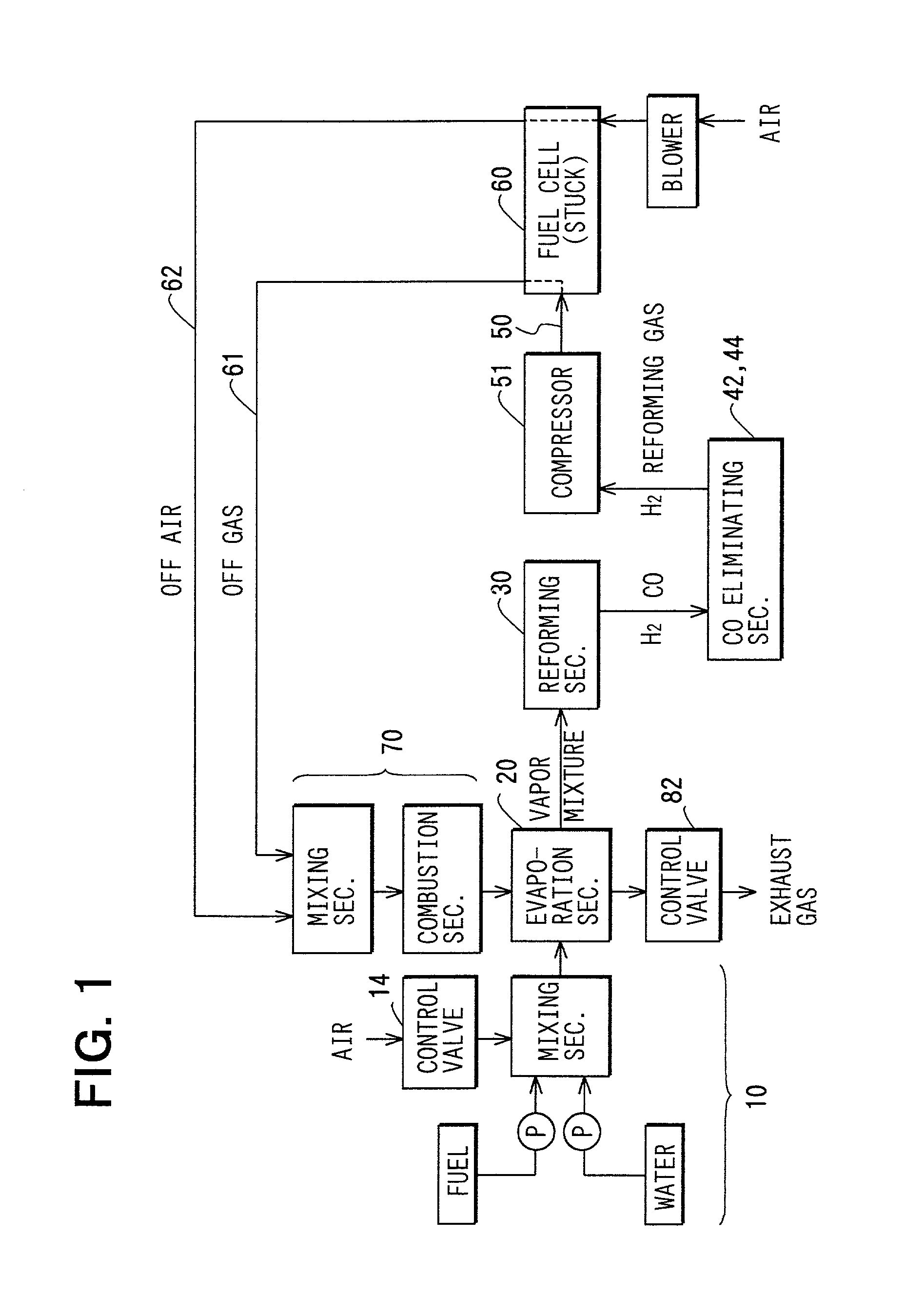
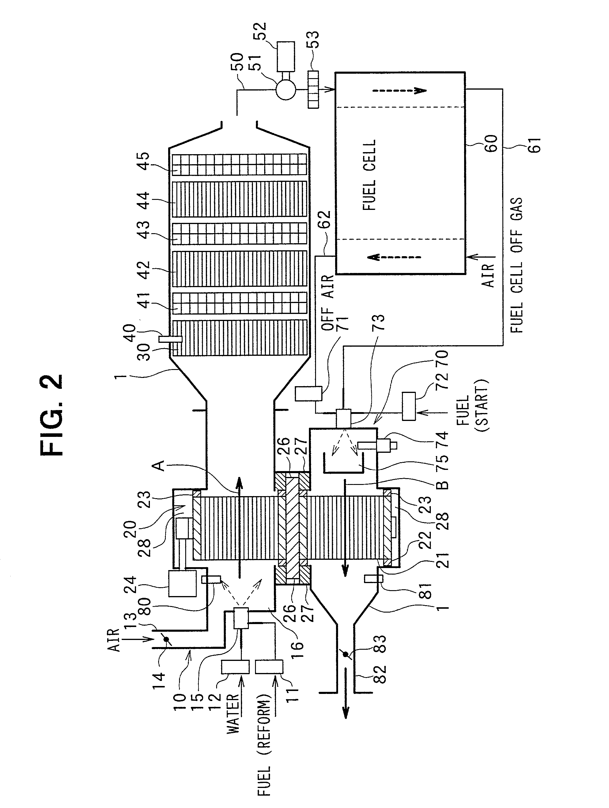
[0050] Referring to FIGS. 1 to 6C, first embodiment of the present invention will be described. FIG. 1 is a block diagram illustrating a general structure of a hydrogen supply device according to first embodiment. FIG. 2 is a conceptual diagram illustrating an arrangement of components of the hydrogen supply device. The hydrogen supply device according to first embodiment supplies hydrogen to a fuel cell 60, which functions as a hydrogen consumption device.

[0051] As shown in FIGS. 1 and 2, the hydrogen supply device according to first embodiment includes a reforming material supply section 10, a heat exchange section (evaporation section) 20, a reforming section 30, a CO eliminating sections 42 and 44, a gas compressor (pressurizing means) 51, and a combustion gas supply section (off gas supply section) 70. Moreover, in the hydrogen supply device, a housing 1 forms a low temperature fluid passage (a reforming material passage) A for passing the reforming mat...

second embodiment

[0113] (Second embodiment)

[0114] Next, referring to FIG. 8, a hydrogen supply device according to second embodiment of the present invention will be described. When comparing second embodiment with the above-described first embodiment, configurations are different in an evaporation section for evaporating a reforming material, and a reforming section for reforming the reforming material. The same members as in the above-described first embodiment are denoted with the same reference numerals, and description thereof is omitted. In second embodiment, the evaporation section and the reforming section compose a heat exchange section.

[0115] As shown in FIG. 8, a rotary heat exchanger includes two rotary thermal storages 21 and 31 so as to have a two-step structure that composes an evaporation section 20 and a reforming section 30. The two rotary thermal storage 21 and 31 are disposed on the same shaft, and are rotary-driven by one driving motor. These rotary thermal storages 21 and 31 ha...

third embodiment

[0122] (Third embodiment)

[0123] Referring to FIGS. 9 to 14, third embodiment of the present invention will be described. FIG. 9 is a block diagram illustrating a general structure of a hydrogen supply device according to third embodiment. FIG. 10 is a conceptual diagram illustrating an arrangement of components of the hydrogen supply device.

[0124] In the low temperature fluid passage A, a first reforming material (a mixture of water and air) supplied from a first reforming material supply section 10a is heated and evaporated at the heat exchange section 20, and a second reforming material (a reforming fuel containing hydride) is mixed therewith in a second reforming material supply section 10b so as to generate a reforming material composed of water, air and reforming fuel. The reforming material is reformed at the reforming section 30 to a reformed gas containing H.sub.2 and CO. After CO is eliminated at the CO eliminating sections 42, 44, it is supplied to the fuel cell 60 as a hy...


PUM

PropertyMeasurementUnit
temperatureaaaaaaaaaa

Abstract

In the hydrogen supply device for producing and supplying hydrogen to a fuel cell, a heat exchange section has a rotary thermal storage through which low and high temperature passages pass. Reforming material is supplied to the low temperature fluid passage on an upstream side of the heat exchange section. A reforming section for producing reformed gas containing hydrogen is located at a downstream side of the low temperature fluid passage. A combustion gas supply section for generating and supplying a combustion gas is located in the high temperature fluid passage. The rotary thermal storage rotates to move alternately between the low and high temperature fluid passages so that heat of the combustion gas flowing in the high temperature fluid conduit is transferred to reforming material flowing in the low temperature fluid conduit. The low temperature fluid passage communicates with the high temperature fluid passage via the fuel cell.

Description

[0001] This application is based upon and claims the benefit of priority of Japanese Patent Applications No. 2000-261092 filed on Aug. 30, 2000, No. 2000-308033 filed on Oct. 6, 2000, No. 2000-343666 filed on Nov. 10, 2000 and No. 2001-130121 filed on Apr. 26, 2001, the contents of which are incorporated herein by reference.[0002] 1. Field of the Invention[0003] The present invention relates to a hydrogen supply device for producing hydrogen due to a reforming reaction of reforming material and supplying the produced hydrogen to a hydrogen consumption device.[0004] 2. Description of Related Art[0005] Conventionally, a hydrogen supply device disclosed in JP-A-11-343101 is known. The conventional hydrogen supply device has a structure that off gas of a fuel cell is combusted in a combustion section for transferring the combustion heat of the combustion gas to reforming material. However, pre-heating and evaporation sections, through which the reforming material passes and in which the...

Claims


Application Information

Patent Timeline
Patent Type & Authority Applications(United States)
IPC IPC(8): B01J8/04B01J19/18B01J19/24C01B3/38C01B3/48C01B3/58F28D19/04H01M8/04
CPCB01J8/04Y10S165/016B01J19/18B01J19/2485B01J2208/00168B01J2208/00309B01J2208/0053B01J2208/00716B01J2219/00006C01B3/384C01B3/48C01B3/583C01B2203/0244C01B2203/0283C01B2203/044C01B2203/047C01B2203/066C01B2203/0805C01B2203/0811C01B2203/0822C01B2203/0827C01B2203/0844C01B2203/0866C01B2203/0883C01B2203/1052C01B2203/1064C01B2203/107C01B2203/1076C01B2203/1205C01B2203/1247C01B2203/1258C01B2203/1276C01B2203/1288C01B2203/142C01B2203/16C01B2203/1695C01B2203/82F28D19/042F28D19/047H01M8/04097H01M8/0618Y02E60/50B01J8/0496Y02P20/10
Inventor KONDO, YASUOTERAO, TADAYOSHIKAWAGUCHI, KIYOSHI
Owner DENSO CORP
Features
  • Generate Ideas
  • Intellectual Property
  • Life Sciences
  • Materials
  • Tech Scout
  • Unparalleled Data Quality
  • Higher Quality Content
  • 60% Fewer Hallucinations
Learn More