Method for the scheduled execution of a target function

a target function and schedule technology, applied in the direction of multi-tasking arrangements, program control, instruments, etc., can solve the problems of not being able to execute simultaneously with one or more other programs on the same processor without detriment to time precision, and not being able to achieve multi-tasking,

Inactive Publication Date: 2002-06-06
NAT INSTR IRELAND RESOURCES
View PDF13 Cites 10 Cited by
  • Summary
  • Abstract
  • Description
  • Claims
  • Application Information

AI Technical Summary

Benefits of technology

0012] The time-dependent value for the expected maximum delay is preferably determined on the basis of the actual delay. The actual delay can be determined by reading the time stamp counter at the beginning of the start function and by subtracting the value (in units of the count register) corresponding to the appearance of the interrupt signal. This measured actual delay should be multiplied by a safety factor that is between 1.2 and 2. However, an upper limit should be set for the maximum delay and thus for the lead time of the interrupt signal. If the delay between the interrupt signal and the execution of the start function is too long, the interrupt request is regularly initiated too early by the method according to the invention. This results in a long runtime of the polling method before the target function is executed. Little computing time remains for other tasks of the multitasking system. This can lock up the operating system. The initial value for the lead time should be determined within a test run in order to keep the possibility of calls of the target function that are too late as low as possible. No call of the target function occurs within the test run, only the actual delay is determined in order to define its maximum value. During the test run, 10-100 calls of the start function should be performed.
0013] Because interrupt inputs are largely reserved for defined functions in modem computers, particularly personal computers, with a plurality of internal and external peripheral devices, it is unlikely that there is an individual, separate interrupt input available for the execution of the method according to the invention. In addition, the interrupt request preferably occurs at discrete times. For this reason, a timer interrupt is used, i.e., an interrupt signal that is triggered by a timer of the computer. The timer interrupt of a personal computer, as a rule, is used by its operating system for various functions. This applies in particular to the timer interrupt with the highest priority (IRQ 0) that controls the internal clock and the processor time slicing for various programs (task scheduler) in IBM compatible PCs of the x86 family, among others. The use of the highest priority timer interrupt has the advantage that the maximum delay has the smallest value.

Problems solved by technology

The disadvantage of the polling method is that it is not capable of multitasking, i.e., it cannot be executed simultaneously with one or more other programs on the same processor without detriment to the time precision.
Pure polling with the highest resolution requires the total computing power of the processor and leaves no computing time available for other programs.
Additional factors that may influence the delay between the appearance of the interrupt signal and the execution of the ISR include the current load on the processor by other tasks running on the processor that temporarily deactivate the interrupt handling of the processor.
However, the exactness of polling is not achievable by using an interrupt request.
The assumption of a delay that is too large would cause, on the statistical average, an unnecessarily long time to be spent with the polling method.
This results in a long runtime of the polling method before the target function is executed.
During this period, the operating system of the computer and the programs executed by it become extremely sluggish and are brought temporarily to a standstill.

Method used


Image

  • Method for the scheduled execution of a target function
  • Method for the scheduled execution of a target function
  • Method for the scheduled execution of a target function

Examples


Embodiment Construction

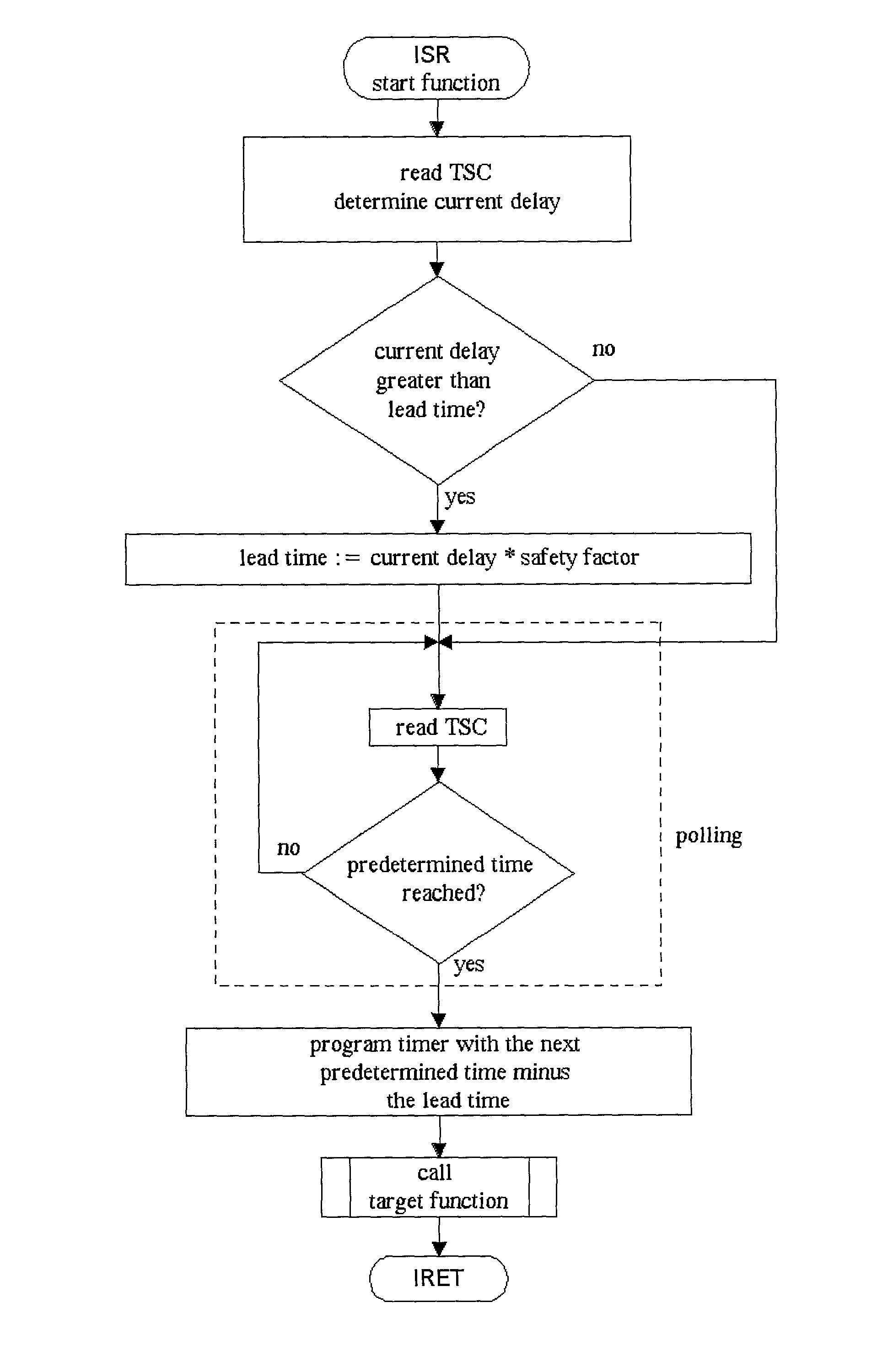
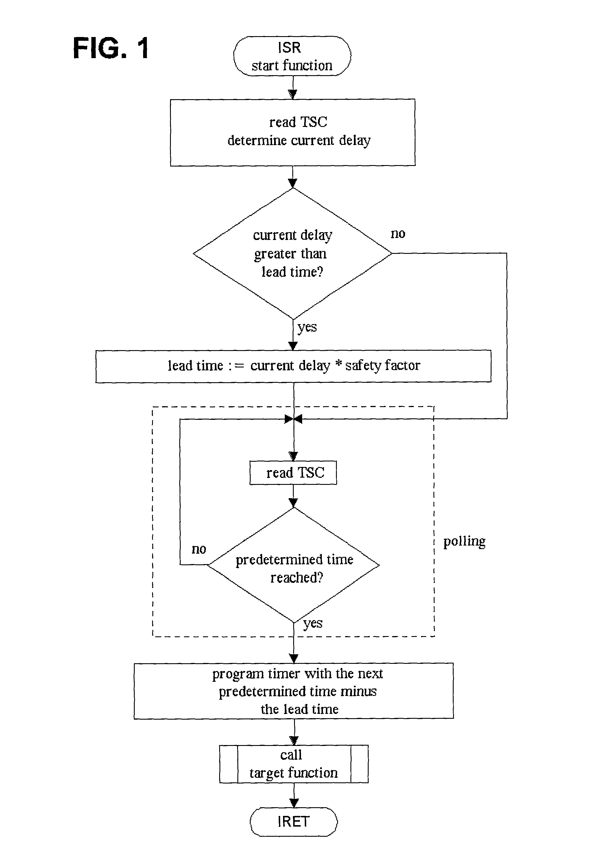
[0027] FIG. 1 shows the principal execution flow of a program using the method according to the invention. As the interrupt service routine, the mentioned start function is called by an interrupt request. This reads the time stamp counter (TSC) and compares the time determined using this value with the time of the interrupt signal. The time difference represents the current delay. If the current delay is longer than the set value of the lead time of the interrupt signal, then the value for the lead time is preferably set to at least the measured current delay. Preferably, a safety factor of 1.2 to 2 is taken into account so that the lead time is longer than the measured current delay.

[0028] Next, the program executes a polling method that continuously reads the TSC and compares the read value with the value representing the predetermined time for the execution of the target function. When the read value corresponds to this reference value, the target function is called. Then the tim...


PUM


Abstract

A method for the scheduled execution of program steps (target function) by the processor of a computer at predetermined times, in which a register of the computer is read repeatedly and this value is compared with a reference value representing the predetermined time, wherein when the read value corresponds to the reference value, the target function is executed in the processor. In the described method, a technique is used that is known by the English term "polling." The disadvantage of the polling method is that it is not suitable for multitasking. This disadvantage is overcome by the present invention. This task is solved such that the reading of the register is performed within a start function that is executed by the processor as an interrupt service routine.

Description

[0001] The invention pertains to a method for the scheduled execution of program steps by means of the processor of a computer at predetermined times, wherein a register of the computer is read repeatedly and its value is compared with a reference value representing the predetermined time. When the read value corresponds to the reference value, the aforementioned program steps are executed by the processor. The sequence of scheduled program steps is designated as a "target function" in the following.DESCRIPTION OF THE RELATED ART[0002] In the aforementioned method, a technique is used that is known by the term "polling." In polling, the value of a register of a computer is continuously compared with a predetermined value and when the predetermined value is reached, a certain target function is called. The count value of computer registers that are incremented or decrement at a uniform clock rate by a quartz oscillator always corresponds to a concrete time value. Such registers are d...

Claims


Application Information

Patent Timeline
Patent Type & Authority Applications(United States)
IPC IPC(8): G06F9/48
CPCG06F9/4825
Inventor MULLER, STEFAN KLEMENSBIERWISCH, CLEMENSNACKEN, RUDOLFDIETERLE, ULRICH
Owner NAT INSTR IRELAND RESOURCES
Why Eureka
Try Eureka