Flourescence polarization assay system and method

a technology of polarization assay and polarization assay, which is applied in the direction of fluorescence/phosphorescence, luminescent dosimeter, optical radiation measurement, etc., can solve the problems of degrading accuracy, increasing the readout time and instrument cost, and increasing the cost or complexity of the element without great consequen

a technology of polarization assay and polarization assay, which is applied in the direction of fluorescence/phosphorescence, luminescent dosimeter, optical radiation measurement, etc., can solve the problems of degrading accuracy, increasing the readout time and instrument cost, and increasing the cost or complexity of the element without great consequen

US20020070349A1Inactive Publication Date: 2002-06-13CAMBRIDGE RES & INSTR

Image

  • Flourescence polarization assay system and method
  • Flourescence polarization assay system and method
  • Flourescence polarization assay system and method

Examples


Embodiment Construction

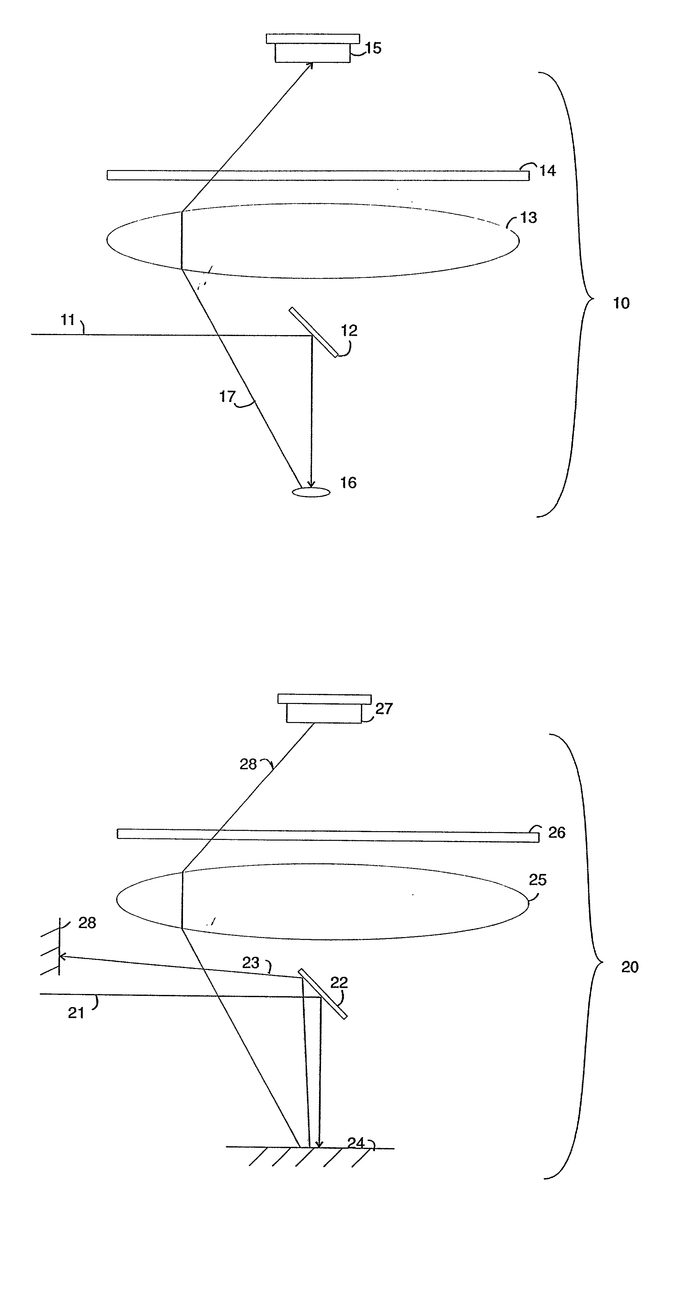
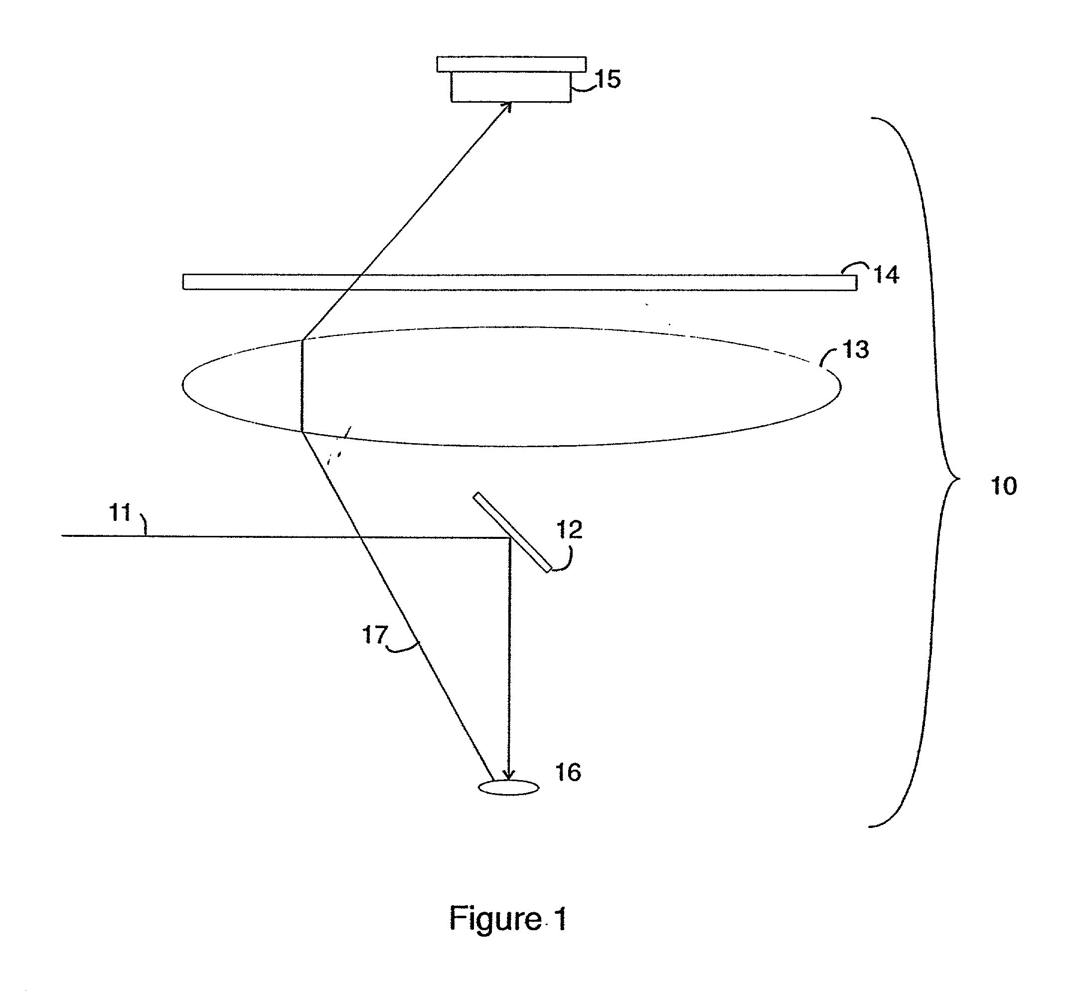
[0052] In this detailed description of the present inventive fluorescence instrument certain terms are synonymous in meaning and interchangeably used. The term waveplate and retarder are both used to denote an optical retarder element having a selected optical retardance. Wavelength band and wavelength range are both used to denote a contiguous range of wavelengths, which typically spans a few nanometers or more, but may be monochromatic in some cases such as when discussing laser light or spectral line emission from lamps. Fluorescence instrument, instrument, fluorescence reader, and plate reader all refer to an instrument for quantifying the amount, polarization, or time-evolution of fluorescent light from a sample.

[0053] FIG. 1 depicts a fluorescence reader 10 in accordance with the present invention. Light rays 11 reflect from a mirror 12 and are directed onto a sample 16. Ideally, the light rays form a relatively compact bundle, so the mirror is small and blocks a negligible po...


PUM

PropertyMeasurementUnit
emission wavelengthaaaaaaaaaa
wavelengthaaaaaaaaaa
wavelengthsaaaaaaaaaa

Abstract

An instrument is disclosed for fluorescence assays which is capable of reading many independent samples at the same time. This instrument provides enhanced throughput relative to single-sample instruments, and is well-suited to use in general fluorescence, time-resolved fluorescence, multi-band fluorescence, fluorescence resonance energy transfer (FRET), and fluorescence polarization. This invention is beneficial in applications such as high-throughput drug screening, and automated clinical testing. Also disclosed are means and methods for a fluorescence polarization measurement which is highly sensitive, inherently self-calibrated, and unaffected by lamp flicker or photobleaching. This fluorescence polarization invention can be practiced on a variety of fluorescence instruments, including prior-art equipment such as microscopes and multi-well plate readers.

Description

[0001] 1. Field of the Invention[0002] The present invention relates to equipment and methods for assaying the amount of optical fluorescence, and the degree of fluorescence polarization, in samples.[0003] 2. Background and Description of the Related Art[0004] Fluorescence Methods and Terminology.[0005] Fluorescence involves exciting a molecular group with light of a first wavelength, causing it subsequently to emit light of a second, longer wavelength. The molecular group is termed a fluorophore, and the first and second types of light are termed "excitation" and "emission" light, respectively. Between excitation and emission, the molecular group is said to be in an excited state. Depending on the molecular group involved, the time spent in the excited state can vary widely, from a few nanoseconds to several microseconds. The duration of the excited state is termed the fluorescence lifetime. It is common to chemically engineer a fluorescent marker compound by grafting a fluorophore...

Claims


Application Information

Patent Timeline
13 Jun 2002
Publication
US20020070349A1
IPC
G01N21/64
CPC
G01N21/6445
Inventors
HOYT, CLIFFORD C.