Vehicle motor-generator apparatus utilizing synchronous machine having field winding

Inactive Publication Date: 2002-06-20
DENSO CORP
View PDF26 Cites 64 Cited by
  • Summary
  • Abstract
  • Description
  • Claims
  • Application Information

AI Technical Summary

Problems solved by technology

However with such an apparatus, a worst-case operating condition occurs when the engine is halted immediately after the vehicle motor-generator apparatus has been running in a condition in which it is generate a substantial level of electric power (so that the synchronous machine is at a high temperature), and the engine is then restarted shortly after having been halted, so that a high level of current must be passed through the field winding of the synchronous machine under a condition of low speed of rotation.
As a result, the maximum allowable temperature of the field winding may be exceeded, so that insulation breakdown or deterioration may occur.
However it is undesirable to have to design such a vehicle motor-generator apparatus on the basis of thermal conditions which occur when the apparatus must supply a large amount of torque during a very short time interval, for the purpose of starting the vehicle engine, since in that case the thermal capacity of the vehicle motor-generator apparatus will be greatly in excess of that which is necessary during the majority of the time that the apparatus is operated, i.e., the configuration of the synchronous machine of the vehicle motor-generator apparatus will be excessively large and heavy.
In the prior art, the problem exists that the field winding of the synchronous machine of the v

Method used


Image

  • Vehicle motor-generator apparatus utilizing synchronous machine having field winding
  • Vehicle motor-generator apparatus utilizing synchronous machine having field winding
  • Vehicle motor-generator apparatus utilizing synchronous machine having field winding

Examples


first embodiment

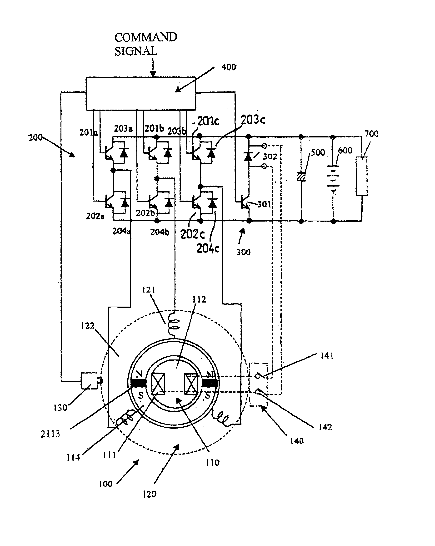
[0067] FIG. 1 shows the overall configuration of a vehicle motor-generator apparatus according to the present invention. This is based on a synchronous machine 100 functioning as a generator-motor, which has both permanent magnets and a field winding. The synchronous machine 100 has a rotor 110 disposed within the inner periphery of a stator 120. The rotor 110 has a first rotor core 112 with a field winding 111 wound thereon, and a second rotor core 114 mounted coaxially with the first rotor core 112 such as to be incapable of rotation with respect to the first rotor core 112, and having permanent magnets 2113 mounted thereon. The rotor 110 is mechanically coupled to the crankshaft of a vehicle engine (not shown in the drawings) by for example a drive belt.

[0068] The stator 120 has a stator core 122 with an inner periphery which is separated by a fixed gap from the outer periphery of the second rotor core 114, and which has a 3-phase armature winding 121 wound thereon. The synchrono...

second embodiment

[0080] A second embodiment will be described, whose overall configuration is as shown in FIG. 5. This configuration differs from that of the preceding embodiment only with respect to the rotor 110 of the synchronous machine 2000, which is not provided with permanent magnets. However it should be understood that the principles described in the following would also apply to a synchronous machine having a field winding and permanent magnets mounted on the rotor.

[0081] The operation of this embodiment with respect to engine starting will be described referring to FIG. 11. Firstly, when engine starting is to be executed by the synchronous machine 2000, power is supplied from the field current supply circuit 300 to the field winding 111, and a field magnetizing force Ff is thereby generated whereby the rotor 110 is magnetized and a field flux .phi.f is thereby induced in the stator 120. Since the field winding 111 has a high value of inductance, a certain amount of time is required before...

third embodiment

[0100] A third embodiment will be described referring to FIG. 13. The overall configuration of the vehicle motor-generator apparatus can be as described for either of the preceding embodiments, so that detailed description will be omitted.

[0101] As can be understood from the description of the preceding embodiment, it is important to have a large value of thermal capacity Q of the rotor of a field winding type of synchronous machine which is used as a vehicle motor-generator. However, a large thermal capacity signifies that the rotor must be large in size. An embodiment will be described whereby thermal transfer is increased between the field winding 111 and the armature winding 121, i.e., whereby the temperature differential between these is reduced. The effective thermal capacity of the armature winding 121 can thereby be increased. FIG. 13 is a partial cross-sectional view of the rotor of the synchronous machine of this embodiment. As shown, the field winding 111 is held within a...


PUM


Abstract

A vehicle motor-generator apparatus based on a field winding type of synchronous machine coupled to a power inverter and a battery, wherein the synchronous machine is controlled to operate as a motor to perform engine starting and thereafter be driven by the engine as an electrical generator, wherein during a short time interval at the commencement of engine starting, the armature winding of the synchronous machine is driven by a current such that magnetic flux is produced by the armature winding acting in the same direction as magnetic flux produced by the field winding, to thereby achieve increased torque during the time when maximum torque is required. In addition, the supplied field current is set at a maximum value during only an initial period when engine starting begins, until the first compression stroke of the engine has been completed, and thereafter set to a reduced value until the completion of engine starting, thereby reducing the amount temperature rise within the field winding during engine starting, while ensuring a sufficiently high value of initial torque.

Description

BACKGROUND OF INVENTION[0001] 1. Field of the Invention[0002] The present invention relates to a type of rotary electrical device of the type known as a synchronous machine, and in particular to a synchronous machine for use in a vehicle motor-generator apparatus that is controllable for selectively performing electric motor and electric power generation functions.[0003] 2. Description of Prior Art[0004] There have been proposals made in the prior art to use a synchronous machine of the type having a field winding in a motor-generator apparatus of a vehicle which is driven by an internal combustion engine (referred to in the following simply as the engine), so that a single rotary electrical device can be employed as a motor for the purpose of starting the engine and also as a generator (driven from the engine) for supplying electric power for charging the vehicle battery while the engine is running. Alternatively, such a vehicle motor-generator apparatus could also be utilized to p...

Claims


Application Information

Patent Timeline
IPC IPC(8): H02J7/14H02P9/02
CPCF02N11/04F02N2300/104H02P9/02H02J7/1461H02J7/1492H02J7/1453H02J7/007192H02J7/0047
Inventor KAJIURA, HIROAKI
Owner DENSO CORP
Why Eureka
Try Eureka