Method for correcting spherical aberration of a projection lens in an exposure system

a projection lens and exposure system technology, applied in the field of exposure system spherical aberration correction, can solve the problems of spherical aberration as mentioned above, raise the cost of exposure, and the spherical aberration cannot be reduced

Inactive Publication Date: 2002-06-20
NEC ELECTRONICS CORP
View PDF0 Cites 11 Cited by
  • Summary
  • Abstract
  • Description
  • Claims
  • Application Information

AI Technical Summary

Problems solved by technology

However, it is also known that a higher numerical aperture of the projection lens narrows the focus depth, and accordingly, only a miner deviation or shift of the focal point causes a defect, although the higher numerical aperture improves the resolution as described above.
The spherical aberration as mentioned above raises a problem especially in the exposure system using a phase shift mask.
Thus, the spherical aberration cannot be reduced merely by reducing the best focus shift amount of a pattern or the difference in the best focus shift amount between two different patterns.
The technique described in JP-A-2000-266640 raises the cost for the exposure due to using a pair of phase shift masks having different two-dimensional patterns.
This leads to the fact that correction of the spherical aberration based on the focus difference between the different pattern sizes or the best focus shift amount of the isolated hole pattern does not necessarily suppress the variance of dimensions of the isolated pattern.
Thus, the spherical aberration cannot be correctly reduced if the lower-order component which can be intentionally corrected is not measured separately from the higher-order components in the spherical aberration.
However, since the allowable margin for the focus of the large pattern is wide, it is extremely difficult to obtain an accurate value for the best focus shift amount.

Method used


Image

  • Method for correcting spherical aberration of a projection lens in an exposure system
  • Method for correcting spherical aberration of a projection lens in an exposure system
  • Method for correcting spherical aberration of a projection lens in an exposure system

Examples


Embodiment Construction

[0044] Before describing the preferred embodiment of the present invention, the principle of the present invention will be described for a better understanding of the present invention.

[0045] The present inventor found the following facts in the procedure for solving the above problem of the conventional techniques for measuring the spherical aberration.

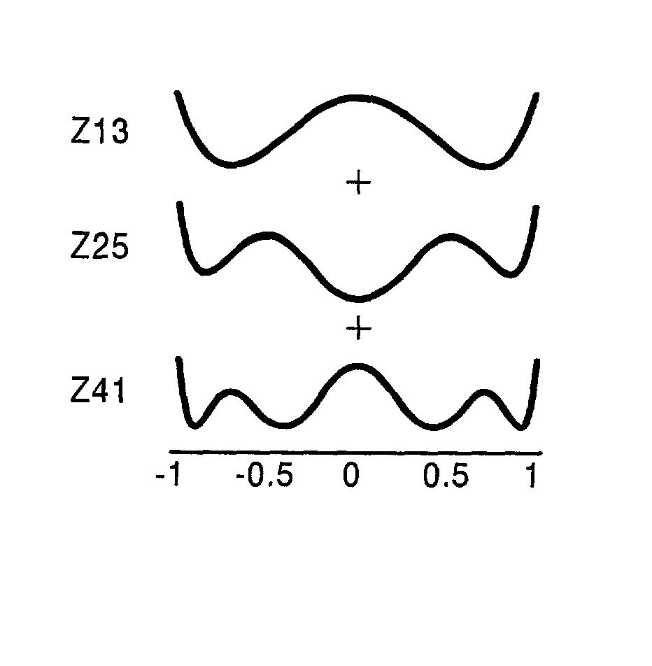
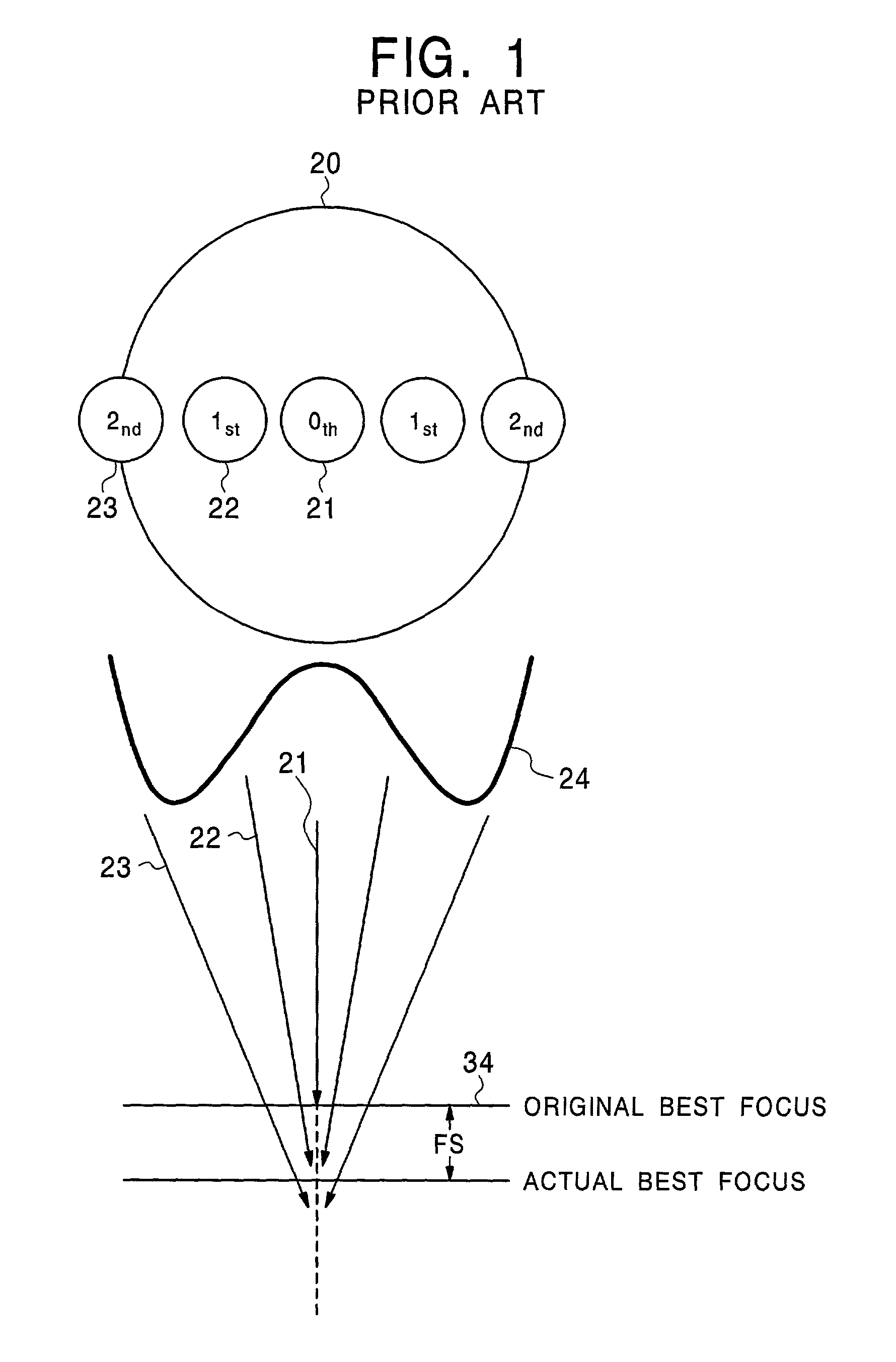
[0046] FIG. 4A includes a schematic top plan view of respective components 21, 22 and 23 of a diffracted light on a pupil surface of a projection lens 20, and a graph 25 of an example of the spherical aberration, which may be observed for the diffracted light shown and is plotted on the ordinate against the coordinate of the pupil surface 20 normalized with the numerical aperture and plotted on abscissa. FIG. 4B is a graph for the respective components of the spherical aberration depicted in FIG. 4A, showing the contribution of the respective components to the total spherical aberration.

[0047] As described before, the components of t...


PUM

PropertyMeasurementUnit
sizesaaaaaaaaaa
sizesaaaaaaaaaa
HT transmittanceaaaaaaaaaa

Abstract

A method for correcting a spherical aberration of a projection lens in an exposure system includes the step of measuring a best focus shift amount by using an exposure light passed by a half-tone phase shift mask having a specific configuration, and correcting the spherical aberration of the projection lens based on the best focus shift amount measured. The half-tone phase shift mask has therein an array of square hole patterns arranged at a pitch P and each having a pattern size of M, P and M satisfying the following relationships: <paragraph lvl="0"><in-line-formula>0.8lambd/(2xNA)<=M<=1.2lambd/(2xNA); </in-line-formula><paragraph lvl="0"><in-line-formula>{lambd/(PxNA)}+sigma<=1; and </in-line-formula><paragraph lvl="0"><in-line-formula>{2xlambd/(PxNA)}-sigma>=1, </in-line-formula>wherein lambd, sigma and NA are wavelength and coherence factor of the exposure light and numerical aperture of the projection lens, respectively.

Description

[0001] (a) Field of the Invention[0002] The present invention relates to a method for correcting the spherical aberration of a projection lens in an exposure system and, more particularly, to a method for correcting the spherical aberration based on the best focus shift amount.[0003] (b) Description of the Related Art[0004] In a fabrication process for semiconductor devices, the pattern of the semiconductor devices is generally obtained by using a photolithographic technique to form an etching mask on a subject film to be patterned.[0005] More specifically, a photoresist film is first formed on a subject film to be patterned, such as an interconnect layer or an insulation layer, followed by patterning the photoresist film by an exposure system using the photolithographic technique to form the etching mask. The underlying subject film is then patterned by an etching technique, such as a plasma-enhanced etching technique, using the etching mask. Examples of the exposure system used th...

Claims


Application Information

Patent Timeline
Patent Type & Authority Applications(United States)
IPC IPC(8): G02B27/00G01M11/02G03B21/00G03F7/20H01L21/027
CPCG02B27/0025G03F7/706G03B21/00
Inventor MATSUURA, SEIJI
Owner NEC ELECTRONICS CORP
Why Eureka
Try Eureka