Charging system and battery pack
- Summary
- Abstract
- Description
- Claims
- Application Information
AI Technical Summary
Benefits of technology
Problems solved by technology
Method used
Image
Examples
first embodiment
[0053] The charging principle of the first embodiment will be described below with reference to FIG. 6. In FIG. 6, a battery temperature rise value is plotted against the ordinate and the charging time is plotted against the abscissa. Curve L in the figure represents the temperature rise values at charging completion corresponding to the charging time, those values being observed when charging was conducted so that the temperature rise value was constant. For example, when the electric current was controlled so that the battery temperature that initially was 20.degree. C. reached 53.degree. C. (temperature rise value of 33 deg), the charging time was 20 min, when the electric current was controlled so that the battery temperature reached 43.degree. C. (temperature rise value of 23 deg), the charging time was 30 min, and when the electric current was controlled so that the battery temperature reached 78.degree. C. (temperature rise value of 58 deg) the charging time was 10 min.
[0054]...
second embodiment
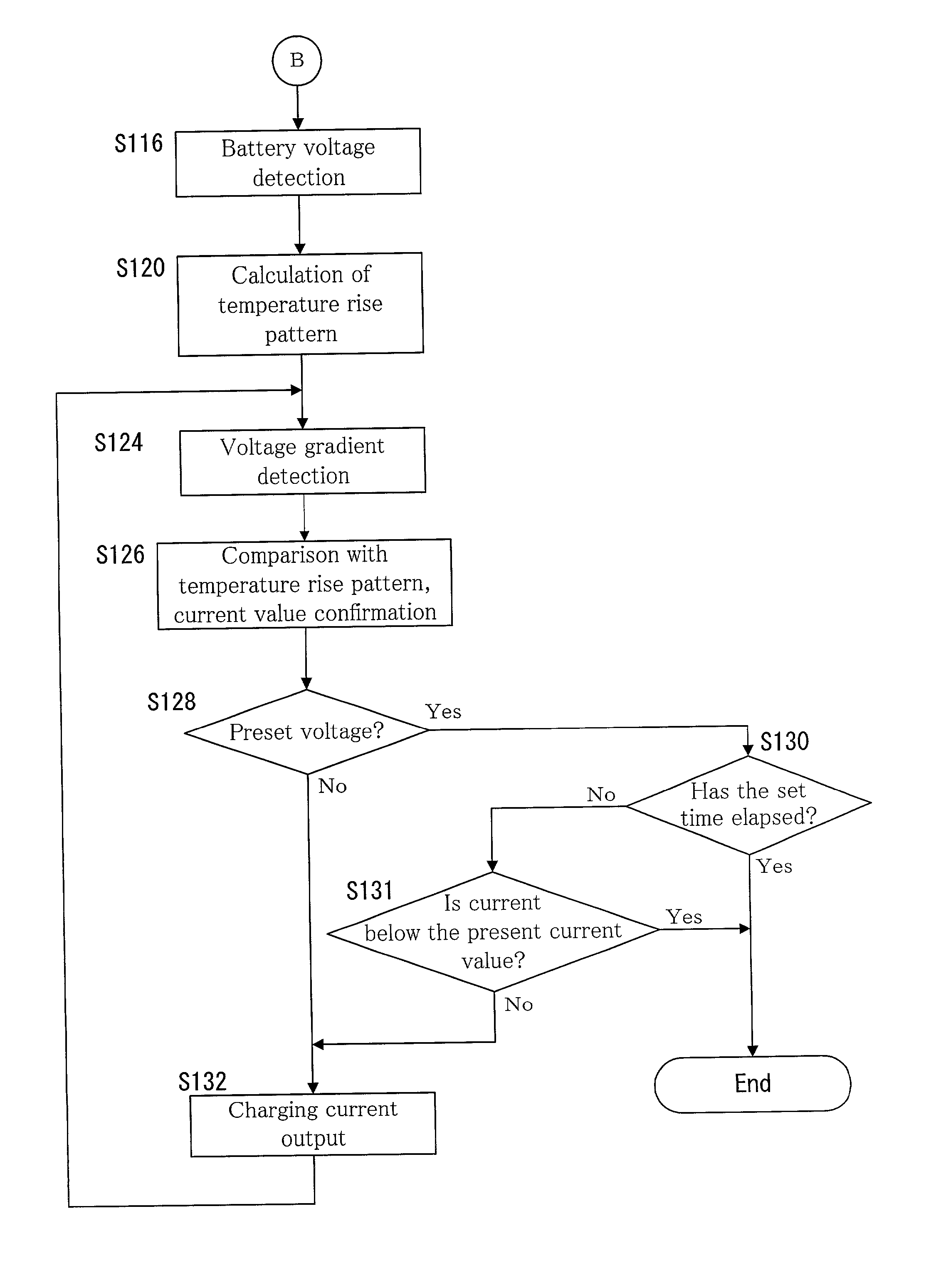
[0078] Specific charging control in the charging device of the second embodiment will be described below with reference to FIG. 10.
[0079] [Case when Nickel-Hydrogen Battery Pack 50 is Charged by the Charging Device]
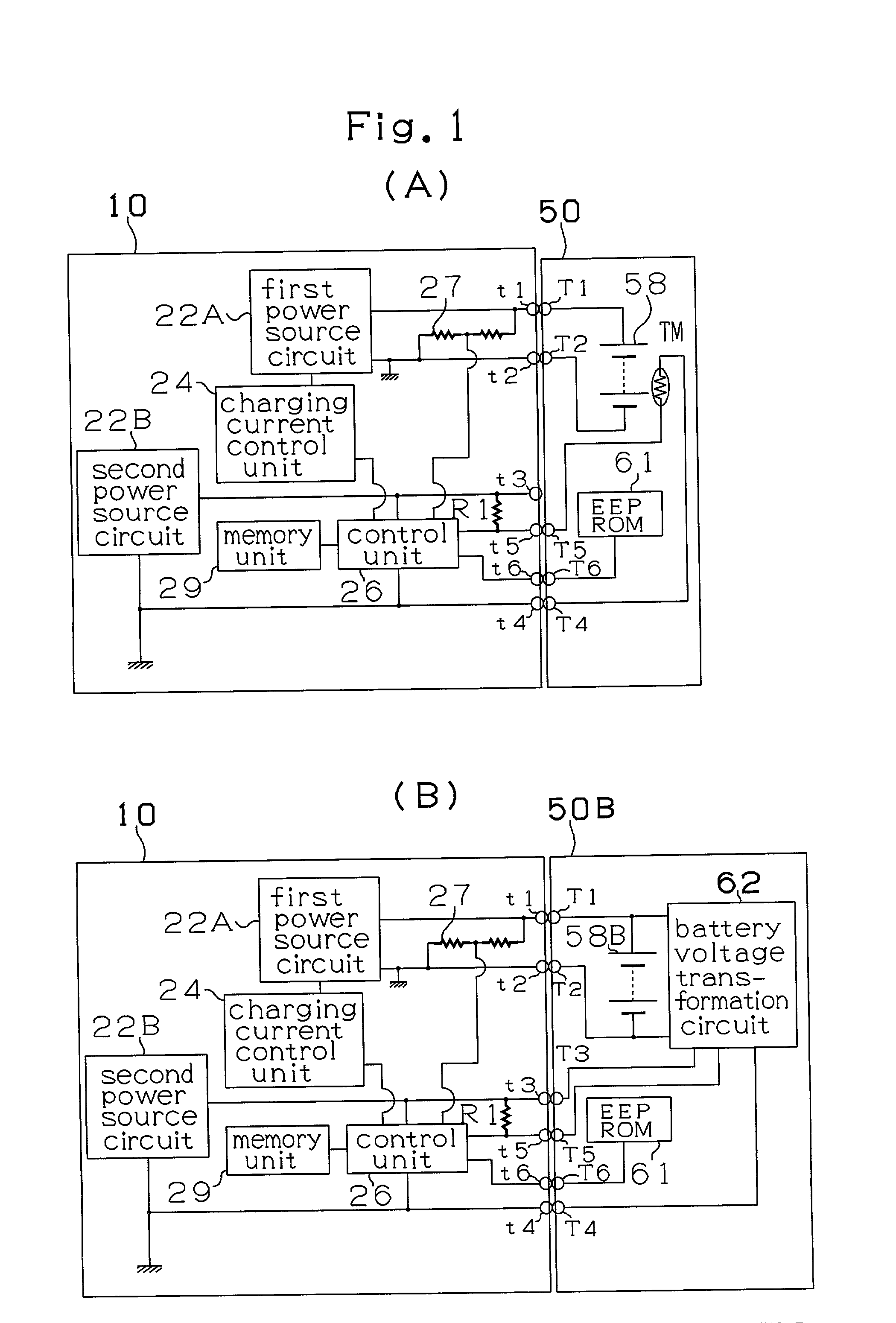
[0080] First, the charging device reads the contents of EEPROM 61 of battery pack 50 (S12). Then, the read-out content is used to determine whether the batteries which are to be charged are in a nickel-hydrogen battery pack 50 or in a lithium ion battery pack 50B (S14). In case of lithium ion batteries (S14: Yes), the program proceeds to the below described charging of lithium ion batteries. On the other hand, in case of nickel-hydrogen batteries (S14: No), control unit 26 detects the temperature of battery pack 50 based on the voltage value determined by the voltage dividing resistance of thermistor TM and resistor R1 (S16). Then, the peak-like temperature rise pattern described above with reference to FIG. 7 is calculated based on data read from EEPROM 61 of nickel-hydr...
PUM
 Abstract
Description
Claims
Application Information
 - R&D
- Intellectual Property
- Life Sciences
- Materials
- Tech Scout
- Unparalleled Data Quality
- Higher Quality Content
- 60% Fewer Hallucinations
Browse by: Latest US Patents, China's latest patents, Technical Efficacy Thesaurus, Application Domain, Technology Topic, Popular Technical Reports.
© 2025 PatSnap. All rights reserved.Legal|Privacy policy|Modern Slavery Act Transparency Statement|Sitemap|About US| Contact US: help@patsnap.com


