Electrophoresis apparatus

a technology of electrophoretic separation and apparatus, which is applied in the direction of electrolysis, diaphragm, fluid speed measurement, etc., can solve the problems of lowering detection accuracy, deteriorating s/n ratio, and inability to safely say the bottom of the channel is flat and smooth

Inactive Publication Date: 2002-07-25
HITACHI LTD
View PDF8 Cites 10 Cited by
  • Summary
  • Abstract
  • Description
  • Claims
  • Application Information

AI Technical Summary

Benefits of technology

[0008] A second object of the present invention is to provide an electrophoresis apparatus which can easily analyze samples from several specimens at a high speed.

Problems solved by technology

Accordingly, the bottoms of the channels cannot be safely said to be flat and smooth.
Due to such a limitation caused by the optical system, there have been raised such problems of deteriorating the S / N ratio caused by background light such as scattered light or stray light, and lowering the accuracy of detection.
Thus, the time of irradiation of the laser beam onto each of the channels becomes shorter, and accordingly, a sample therein cannot be fully excited so that sufficient detection sensitivity would be unavailable.
Further, there would be raised such problem that a variation in the time of fluorescence cannot be detected on a real time base.
Further, the provision of a movable mirror and a complicated optical system are inevitably required for scanning with a laser beam, thereby it would cause the apparatus to be expensive and large-sized

Method used


Image

  • Electrophoresis apparatus
  • Electrophoresis apparatus
  • Electrophoresis apparatus

Examples


Embodiment Construction

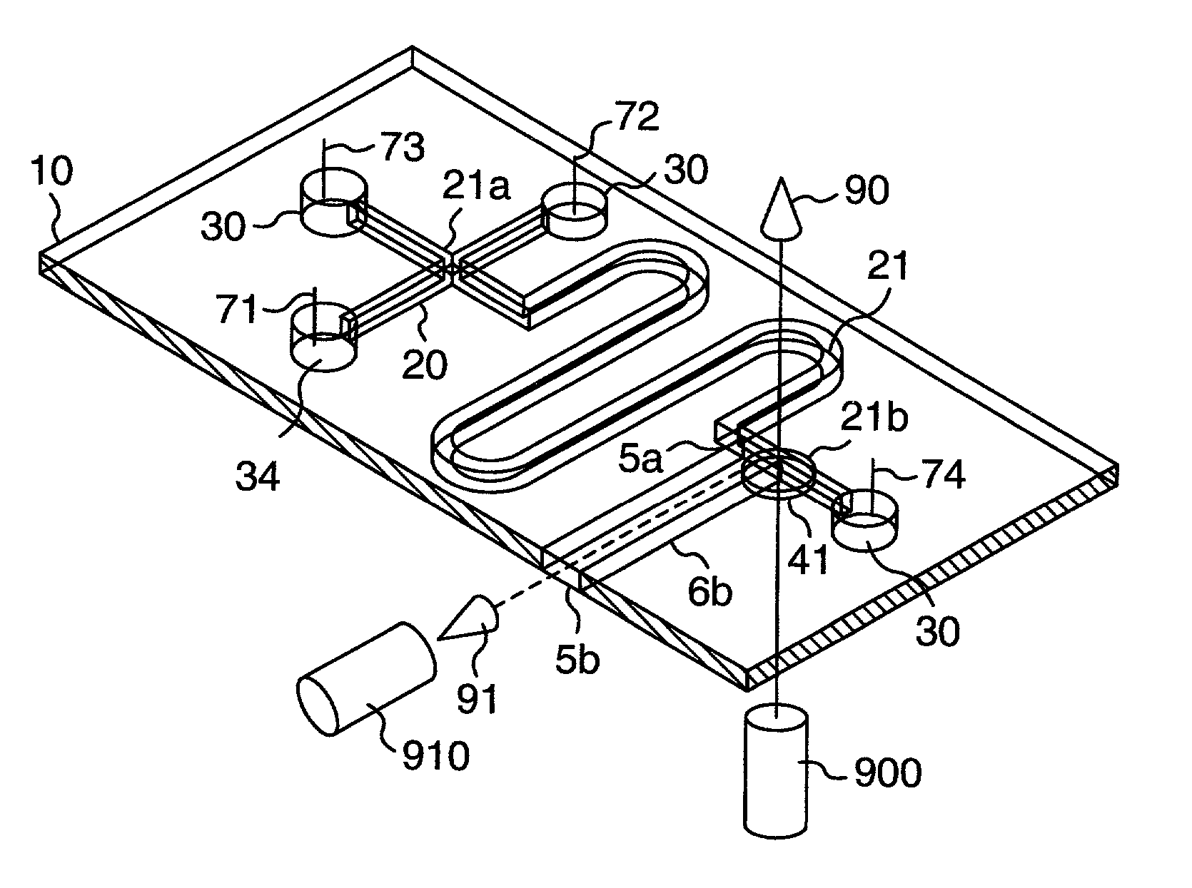
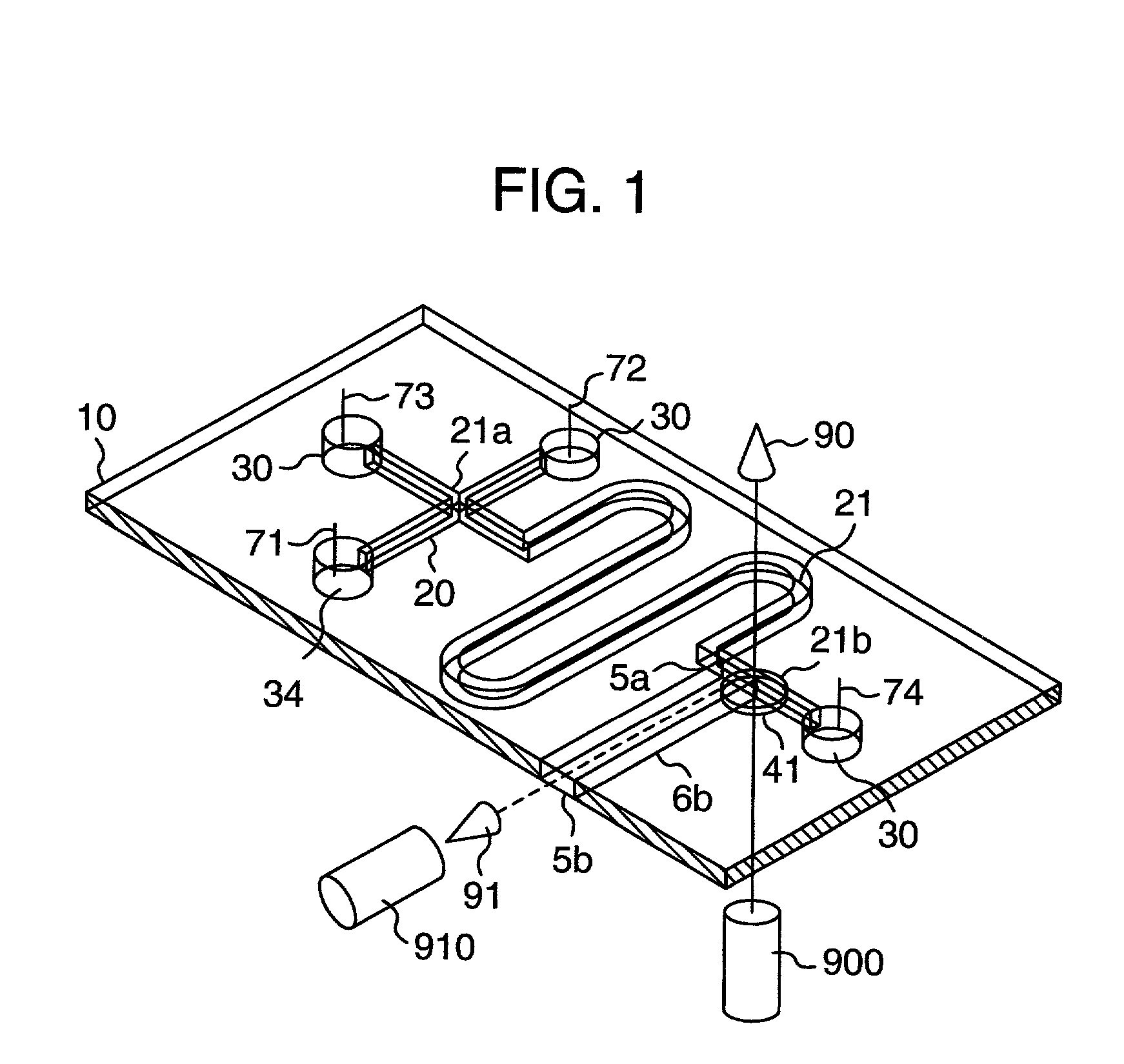
[0021] Referring to FIG. 1 which is a perspective view illustrating a channel substrate in an electrophoresis apparatus in an embodiment of the present invention, a planar plate 10 is formed therein with sample channels 20, a separation channel 21, solution reservoirs 30, a sample reservoir 34 and the like. A detecting part is formed, intermediate of the separation channel 21. The separation channel 21 has a bottom part formed therein with an incoming window through which a light beam can be readily introduced into the detecting part from an excitation light source 900. One side wall of the separation channel 1 is formed therein with a first smooth outgoing window 5a through which light can readily be led into the planar plate, and a fluorescence transmission path 6b for transmitting fluorescence toward one side of the planar plate while preventing the fluorescence from leaking is extended from the first outgoing window 5a to the one side of the planar plate, and is terminated with ...


PUM

PropertyMeasurementUnit
thicknessaaaaaaaaaa
heightaaaaaaaaaa
heightaaaaaaaaaa

Abstract

An electrophoresis apparatus in which an electrophoretic channel formed in a planar plate made of a transparent member and having satisfactory flat and smooth surfaces is irradiated with an excitation beam through the bottom surface or the top surfaces of the channel in a direction orthogonal thereto, and fluorescence from a sample is detected through a side surface of the channel, or the channel is irradiated with the excitation beam through a side surface of the channel while fluorescence from the sample is detected through the bottom surface or the top surface of the channel. With this arrangement, background light and stray light can be reduced so as to enhance the accuracy of detection of the electrophoresis apparatus.

Description

[0001] The present invention relates to an electrophoresis apparatus adapted to be used for analyzing protein, peptide, amino acid, neurotransmitter, hormone nucleic acid or the like which is contained in organisms, or a trace substance contained in the environment, foods, chemical or the like.RELATED ART[0002] There has been proposed a technology of electrophoretic separation which is carried out in channels in a planar plate as disclosed in "Ultra-high speed DNA fragment separations using microfabricated capillary array electrophoresis chips" by A. T. Woolley et al, Proc. Natl., 1994, Vol. 91, pages 11348-11352. The device disclosed in this document is composed of two thin planar glass plates which are joined together and one of which is formed therein with a plurality of fine grooves fabricated by etching so as to define channels together with the other planar glass plate matched with the former. These channels include a sample channel for introducing a sample, and a separation c...

Claims


Application Information

Patent Timeline
Patent Type & Authority Applications(United States)
IPC IPC(8): G01N21/64B81B1/00G01N27/447G01N35/08G01N37/00
CPCG01N27/44721G01N27/44791
Inventor YAMAKAWA, HIRONOBUMIYAKE, RYOSASAKI, YASUHIKOKOIDE, AKIRA
Owner HITACHI LTD
Why Eureka
Try Eureka