Apparatus and method for conveying items

a technology of items and conveyor belts, applied in the direction of transportation and packaging, packaging, packaging goods, etc., can solve the problems of consumption and wear, damage, consumption and wear of items, conveyor belts that transport items and related guides, etc., to reduce the consumption of motive power and simplify the present apparatus. the effect of the structure and functional simplification

Inactive Publication Date: 2002-08-15
PULSAR SRL
View PDF0 Cites 15 Cited by
  • Summary
  • Abstract
  • Description
  • Claims
  • Application Information

AI Technical Summary

Benefits of technology

[0016] In this way it is possible to maintain, at least in the initial part of the conveying apparatus, a conveying speed that is not excessively high, allowing to obtain sufficiently low consumption and wear to the items and the belt. Said speed being at the same time sufficiently high to attain a considerable average conveying speed.
[0018] Moreover, especially if short items are to be conveyed, the risk of upsetting them along the line is minimised, avoiding to the utmost extent the need for interventions on the part of the personnel.
[0020] Moreover, a considerable structural and functional simplification of the present apparatus with respect to known apparatuses is obtained, eliminating, among other things, the presence of dedicated stopping and accelerating units.
[0021] A lower consumption of motive power with respect to known devices is also achieved.
[0023] Since said items are to be conveyed by being maintained longitudinally grouped together, in such away that the distance between adjacent items is such that if an item rotates or is upset, it comes in contact with an item of said group that is adjacent thereto, it is possible to prevent said upsets of the items from occurring. Hence one avoids, on one hand, the need for intervention on the personnel's part and, on the other hand, any stops to the line that feeds the items. In short, a very high production is obtained, exceeding that of known conveying systems.

Problems solved by technology

Such a traditional manner of operating on the items, however, presents numerous drawbacks.
A first drawback concerns the damage, consumption and wear whereto the items are subjected, and consequently also the conveyor belts that transport them and the related guides.
Such consumption and wear are caused by the high rubbing stresses between the items and the means for transporting them, stresses whose main cause is the high levels of acceleration and speed reached in said known systems.
Such damage to the rolls is aggravated even further by the locking action provided by mechanical assemblies for stopping the rolls used in known conveying lines.
Another drawback concerns the upsets whereto a certain number of such conveyed items are subjected, especially those presenting modest length, again due to such excessive accelerations and speeds.
Such removal actions, however, cannot always be timely, so in spite of them the items cause clogging along the line, resulting in consequent stops of the line itself, with the deriving efficiency losses and slow average speeds of advance of the products.
It has been observed that such a distancing of the items is a cause for the upset of the items themselves along the conveying line.
A further negative aspect also stems from an excessive use of motive force necessary to subject the products to such high levels of speed and acceleration, whereby it is attempted to overcome the normally provided stops of the items themselves or the stops caused by the upsetting of items along said line.

Method used


Image

  • Apparatus and method for conveying items
  • Apparatus and method for conveying items
  • Apparatus and method for conveying items

Examples


embodiment 10

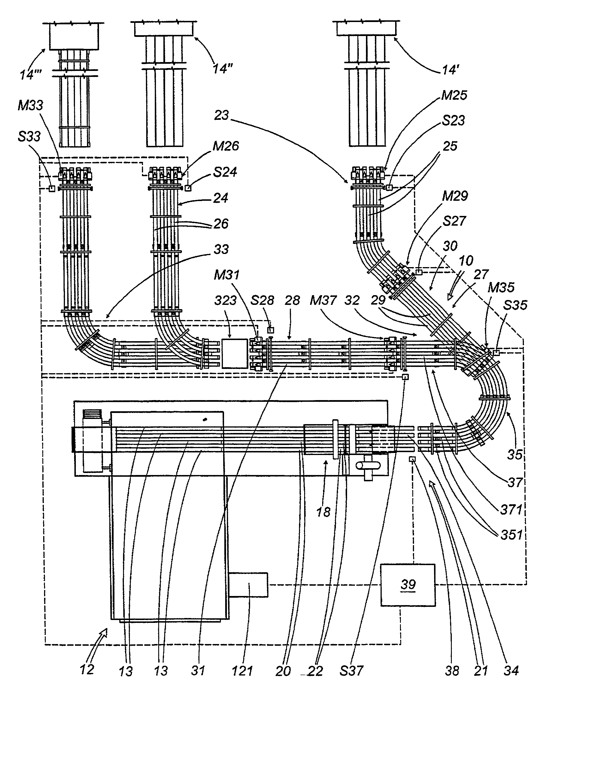
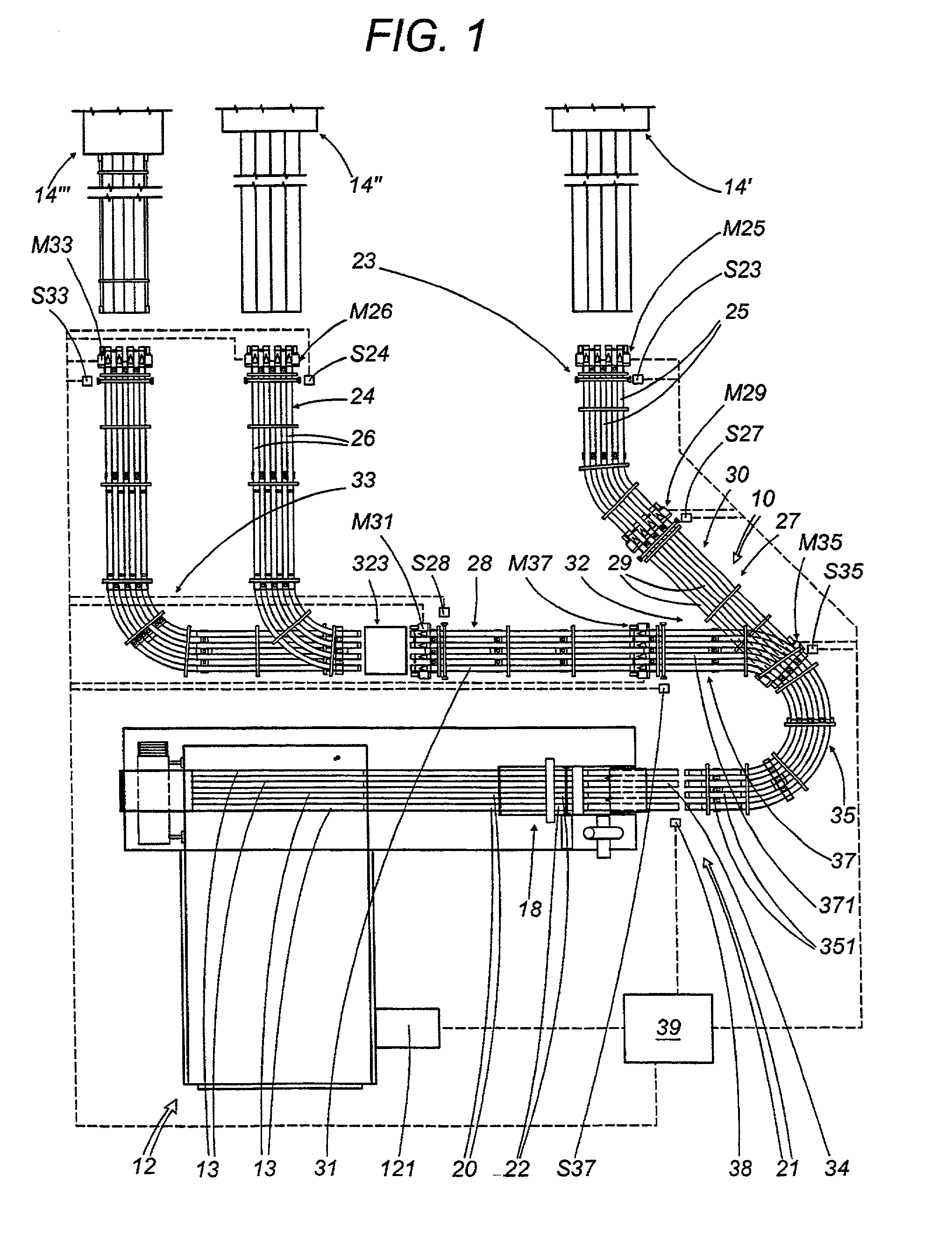
[0035] FIG. 1 shows a system using the first preferred embodiment 10 of conveying apparatus of the present invention. The system comprises a machine 12 for working said items situated upstream, which provides said products or items--in the form of rolls of paper, plastic or similar material obtained starting from respective elongated bodies, or sticks (indicated in FIG. 1 with the numeric reference 13)--by means of equidistant transverse cuts in said stick 13 and, downstream of this machine, a plurality, in particular three machines for treating said items indicated respectively with the numeric references 14', 14" and 14'", in particular in the form of machines for packaging said items which receive said items in a substantially already grouped condition and package them in a respective container, generally constituted by a wrapping film made of plastic material.

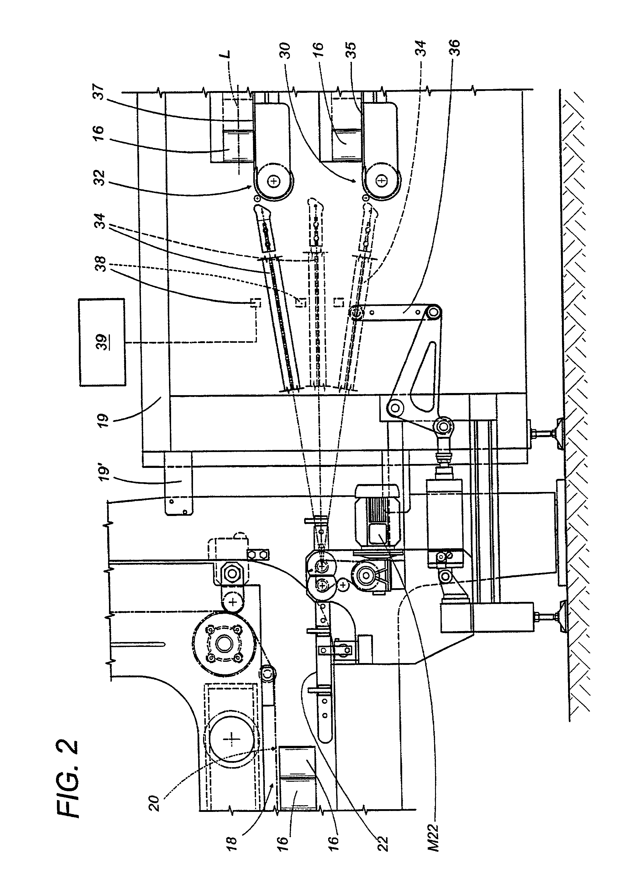
[0036] As shown particularly in FIG. 2, said rolls with substantially cylindrical shape thus present a respective longitu...

first embodiment

[0071] In accordance with FIGS. 5 through 7 of the accompanying drawings, it can be observed that the apparatus for conveying items designated with the reference P in these figures, comprises a line for transporting said items which can be similar to that of the first embodiment, whereof only the initial part designated with the numeric reference 15' is shown in the figures. The line is able to transport said items P from a machine 12 for working said items situated upstream, where a series of rolls made of paper material are provided starting from sticks or reels of larger dimensions, to a series of packaging machines positioned downstream, which are not expressly shown in the accompanying figures.

[0072] In practice, said working machine 12 situated upstream advances and cuts simultaneously one or more reels of paper material, to obtain therefrom a series of individual rolls of paper material, destined prevalently to household use, which are advanced at a predefined speed, exemplif...


PUM


Abstract

The invention relates to a circuit arrangement for supplying a discharge lamp with a direct current, provided with: input terminals for connection to a supply voltage source, a circuit portion I coupled to the input terminals for generating a DC voltage from the supply voltage delivered by the supply voltage source, said circuit portion being provided with output terminals between which the DC voltage is present during operation, a first branch comprising capacitive means and interconnecting the output terminals, a second branch comprising a series arrangement of second capacitive means and an impedance and shunting the first branch, and a load branch which shunts the series arrangement and which comprises terminals for connecting a discharge lamp. According to the invention, the second branch is in addition provided with a diode. It is achieved thereby that a discharge lamp operated by means of the circuit arrangement stabilizes satisfactorily after ignition by means of a current supplied by the second capacitive means via the impedance.

Description

[0001] The present invention relates to a method and an apparatus for conveying items.[0002] Said items being preferably, but not exclusively, in the form of rolls with substantially cylindrical shape obtained by transversely cutting a single body or elongated stick and having a respective longitudinal axis, which are advanced along a longitudinal path of advance, preferably, with its own axis oriented according to the direction of advance.[0003] Preferably, but not exclusively, such items are in the form of rolls of paper, plastic, metallic, or similar material destined mainly to household use, for instance rolls of toilet paper, absorbing paper, plastic film or aluminium foil or others for wrapping food products and other items.[0004] The present conveying apparatus is positioned between a working machine situated upstream, such as a machine for cutting and separating into items from said stick or elongated body, and one or more machines for working said items, such as machines fo...

Claims


Application Information

Patent Timeline
Patent Type & Authority Applications(United States)
IPC IPC(8): B65B25/14B65B35/44
CPCB65B25/146B65B25/148B65B35/44B65B65/003
Inventor FRANZAROLI, MASSIMO
Owner PULSAR SRL
Why Eureka
Try Eureka