Liquid crystal display apparatus

a display device and liquid crystal technology, applied in the direction of identification means, instruments, polarising elements, etc., can solve the problems of difficult formation, inability of reflection and inability of transmission display units to recognize display in a bright environmen

Inactive Publication Date: 2002-08-29
PANASONIC LIQUID CRYSTAL DISPLAY CO LTD +1
View PDF6 Cites 38 Cited by
  • Summary
  • Abstract
  • Description
  • Claims
  • Application Information

AI Technical Summary

Problems solved by technology

The reflection display unit, however, becomes incapable of recognizing the display in a dark environment such as a dark room.
The transmission display unit, however, becomes incapable of recognizing the display under a bright environment where, e.g., the intensity of the interfacial reflection light is stronger than that of the backlight light.
On the other hand, on the lower side of the reflection-type liquid crystal display apparatus, it is difficult to form, as one and the same layer, a reflection electrode for applying a voltage to the reflection display unit and a transparent electrode for applying a voltage to the transmission display unit.
This condition results in a difference in the liquid crystal layer thickness between the reflection display unit and the transmission display unit, thereby making it impossible to obtain excellent displays on both the reflection display and the transmission display.

Method used


Image

  • Liquid crystal display apparatus
  • Liquid crystal display apparatus
  • Liquid crystal display apparatus

Examples


1st embodiment

[0057] 1st Embodiment

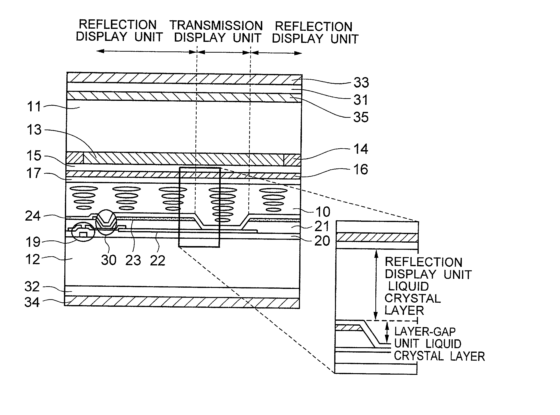
[0058] FIG. 5 illustrates a liquid crystal display apparatus according to the present embodiment. The liquid crystal display apparatus includes a first substrate 11, a liquid crystal layer 10, and a second substrate 12, and the liquid crystal layer is held in being sandwiched between the first substrate and the second substrate. The first substrate has, on the side in closer proximity to the liquid crystal layer, a color filter 13, a black matrix 14, a leveling layer 15, a common electrode 16, and a first orientation film 17. Also, the second substrate has, on the side in closer proximity to the liquid crystal layer, a thin film transistor 19 and a second orientation layer 24. The thin film transistor 19, which is anti-staga type, is connected to a scanning lines, a signal line, a reflection electrode 23, and a transparent electrode 22. The scanning lines and the signal lines are insulated by a first insulating layer 20, and the signal lines and the reflection e...

2nd embodiment

[0078] 2nd Embodiment

[0079] In the liquid crystal display apparatus illustrated in the 1st Embodiment, the thickness of the second insulation layer 21 is increased up to 0.8 .mu.m. This increases the distance between the transparent electrode and the reflection electrode to decrease the capacitance coupling between the both, thereby making it possible to enhance the uniformity in the display.

[0080] Moreover, the lower-side polarizer 34 and the lower-side phase plate 32 are located under the second substrate 12. The second insulating layer 21 is 0.8 .mu.m thick and the diffusion reflection electrode 23 is 0.2 .mu.m thick, and consequently the layer-gap between the reflection display unit and the transmission display unit is equal to 1.0 .mu.m. Also, the birefringence of the liquid crystal material at the wavelength of 633 nm is equal to 0.072. By substituting these values into the equation (2), the angle formed between the transmission axis of the lower-side polarizer 34 and the reta...

3rd embodiment

[0084] 3rd Embodiment

[0085] In the liquid crystal display apparatus illustrated in the 1st Embodiment, the second insulation layer 21 has been left without being removed in the transmission display unit. FIG. 7 is a cross-sectional view for illustrating a liquid crystal display apparatus in the present embodiment. As illustrated in FIG. 7, a configuration has been employed where the upper surface of the transparent electrode 22 is covered with the second insulation layer. In the case where, just like the 1st Embodiment, the second insulation layer 21 is removed in the transmission display unit, the layer-gap equivalent to the thickness of the second insulation layer 21 appears between the reflection display unit and the transmission display unit. This results in a possibility that a display defect such as domain occurs. In order to prevent the display failure like this, the second insulating layer 21 must be etched with a taper of about 45.degree. associated therewith, instead of et...


PUM

PropertyMeasurementUnit
absorption axis azimuth-angleaaaaaaaaaa

Abstract

The liquid crystal display apparatus includes a liquid crystal layer 10 and a liquid crystal driving unit 19 which are held in being sandwiched between a pair of opposed boards 11, 12, and polarization plates 33, 34 and phase plates 31, 32 which are located on the upper side and on the lower side, respectively. Moreover, a pixel of the liquid crystal display apparatus includes the reflection display unit whose reflectivity's applied voltage characteristic is the normally-closed type and the transmission display unit whose layer thickness is thicker than that of a liquid crystal layer constituting the reflection display unit. Furthermore, the polarization plate 34 and the phase plate 32 located on the lower side of the opposed boards form an elliptical polarization plate, thereby converting, into a circularly-polarized light, a backlight light at a point-in-time of having passed through a liquid crystal layer's portion corresponding to a difference in the layer thickness between the liquid crystal layers.

Description

[0001] 1. Field of the Invention[0002] The present invention relates to a liquid crystal display apparatus, and more particularly to a liquid crystal display apparatus including a reflection display unit and a transmission display unit within one pixel.[0003] 2. Description of the Prior Art[0004] One type of the reflection-type liquid crystal display apparatuses has a reflection display unit and a transmission display unit within one pixel. The reflection display unit performs the display by reflecting, using a reflection plate, the light incoming from the surroundings. Since the reflection display unit has a fixed contrast ratio independently of the brightness of the surroundings, it offers an advantage of making it possible to obtain an excellent display under an environment ranging from outdoors to indoors at the time of sunny weather. The reflection display unit, however, becomes incapable of recognizing the display in a dark environment such as a dark room.[0005] Meanwhile, the...

Claims


Application Information

Patent Timeline
Patent Type & Authority Applications(United States)
IPC IPC(8): G02F1/1335G02B5/30G02F1/13363G09F9/00
CPCG02F1/133555G02F1/13363G02F2202/40G02F2413/02
Inventor ITOU, OSAMUKOMURA, SHINICHI
Owner PANASONIC LIQUID CRYSTAL DISPLAY CO LTD
Why Eureka
Try Eureka