Virtual ripple generation in switch-mode power supplies

a power supply and ripple technology, applied in the direction of power conversion systems, dc-dc conversion, instruments, etc., can solve the problems of linear regulators that are inefficient, high-end microprocessors can consume in excess of 80 watts of power and operate at 2 vdc, and can not provide dramatic performance gains, so as to prevent undesirable voltage overshoots and compensate droop

Inactive Publication Date: 2002-09-12
SEMTECH CORP
View PDF0 Cites 107 Cited by
  • Summary
  • Abstract
  • Description
  • Claims
  • Application Information

AI Technical Summary

Benefits of technology

0011] The virtual ripple generator includes one or more ramp generators synchronized with the inductor switching operations of the associated voltage regulator. Nominally, the virtual ripple generator includes a ramp generator for each regulator output phase, with each ramp generator synchronized to the switching of its corresponding regulator output phase. Thus, the virtual ripple generator offers straightforward scaling for use with multiphase voltage regulators. However, the number of ramp generators and the synchronization details may vary as needed in both single- and multi-phase regulator applications. In both single, and multiphase regulation applications, the regulator has the advantage of basing phase switching on generated ripple components, rather than relying on noise-prone actual output ripple. In multiphase applications in particular, this benefit allows the regulator to maintain

Problems solved by technology

Indeed, modern microprocessors could not provide their dramatic performance gains absent today's sophisticated power supplies.
For example, high-end microprocessors can consume in excess of 80 Watts of power and operate at 2 VDC or less.
However, linear regulators are inefficient when required to regulate to an output voltage significantly below their input voltage.
Regulating such primary voltages down to 2 VDC, or even 5 VDC, for high-current loads is impractical using linear regulation.
This error amplification can reduce the bandwidth of the feedback loop, diminishing the switch controller's ability to respond to highly dynamic load chan

Method used


Image

  • Virtual ripple generation in switch-mode power supplies
  • Virtual ripple generation in switch-mode power supplies
  • Virtual ripple generation in switch-mode power supplies

Examples


Embodiment Construction

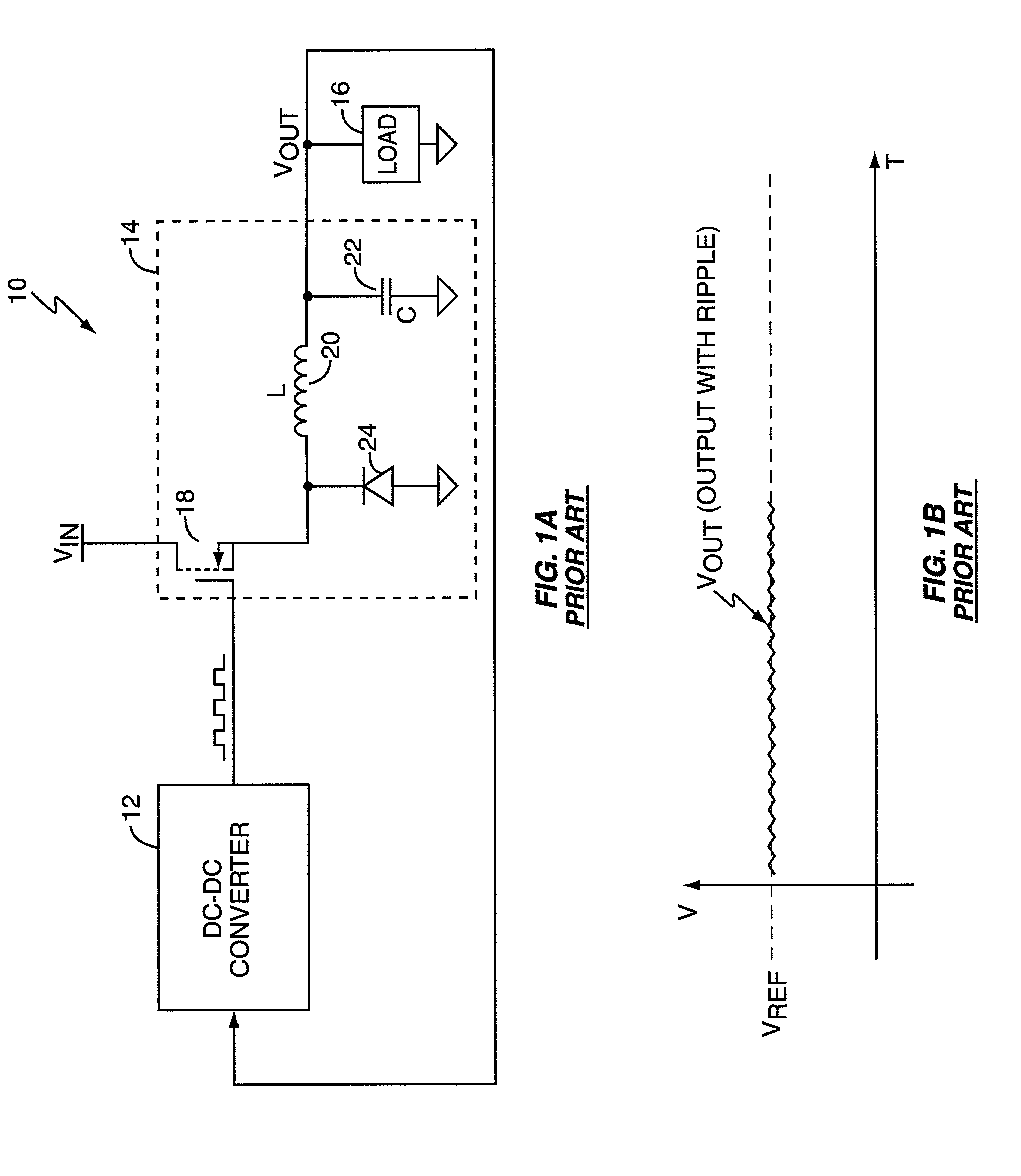
[0024] FIG. 1 depicts a typical electrical system 10, and includes a DC-DC converter 12 driving a single-phase output circuit 14, which in turn provides a regulated output voltage to a load 16. The output circuit 14 includes a switch 18, an output inductor 20, an output capacitor 22, and a circulating diode 24. Those skilled in the art will recognize the basic topology of the converter 12 and associated output circuit 14 as a single-phase "buck" converter configuration. The supply voltage V.sub.IN is at a higher potential than the desired value of V.sub.OUT used to power the load 16. The converter 12 turns switch 18 on and off, connecting and disconnecting the inductor 20 from the supply voltage V.sub.IN and thereby generating V.sub.OUT at the desired potential. V.sub.OUT, or some signal proportional to V.sub.OUT, is fed back to the converter 12 so that it regulates V.sub.OUT to the desired potential. In a buck configuration, V.sub.OUT is at a lower potential than V.sub.IN. Because ...


PUM


Abstract

A system and method provides virtual ripple signal generation for use in voltage regulation applications. Some switch-mode power converters or voltage regulators use output signal ripple to effect voltage regulation. A virtual ripple generator provides this type of voltage regulator with a virtual ripple signal comprising an offset component responsive to actual load voltage, but with a generated AC ripple component of arbitrary magnitude that is independent of actual output signal ripple. Unlike the actual output ripple signal, the generated AC ripple component is not dependent on implementation specifics, such as circuit board layout or output capacitor ESR, and may have its gain set independent of the offset component. The generated AC ripple component is synchronized to the inductor switching actions of the voltage regulator and thus reflects actual inductor phase switching in single and multi-phase regulation applications. Virtual ripple signal generation can include output (load) voltage droop compensation.

Description

BACKGROUND OF THE INVENTION[0001] The present invention relates to power supply regulation, and particularly relates to power converters employing ripple-mode regulation.[0002] Advances in one area of technology often require commensurate advances in supporting technologies to realize the full benefit of the advance. For example, observers of the microprocessor industry are familiar with "Moore's Law," which posits that the complexity of semiconductor devices doubles every two years. Microprocessor development arguably represents the most dramatic illustration of Moore's Law. Pioneering microprocessors released in the 1970's operated at clock speeds well under 500 KHz, and included fewer than five thousand transistors. Modern microprocessors operate at clock speeds in excess of 1 GHz and include millions of transistors. Exploiting these dramatic gains required advances in a host of supporting technologies, from advances in memory technology and circuit fabrication, to advances in po...

Claims


Application Information

Patent Timeline
IPC IPC(8): H02M3/156
CPCH02M3/156H02M2001/0025H02M1/0025
Inventor GROOM, TERRY J.PULLEN, STUART
Owner SEMTECH CORP
Why Eureka
Try Eureka