
Current mirror type bandgap reference voltage generator

a reference voltage and generator technology, applied in logic circuits, instruments, and increasing the degree of modification, can solve the problems of inability to operate stably, low voltage suitable drams, and inability to depend on conventional reference voltage generators, so as to reduce the variation of reference voltage and reduce the minimum operation voltage

Inactive Publication Date: 2002-09-12
SK HYNIX INC
View PDF0 Cites 18 Cited by
  • Summary
  • Abstract
  • Description
  • Claims
  • Application Information

AI Technical Summary

Benefits of technology

[0010] Accordingly, it is a primary object of the present invention to reduce variations of a reference voltage due to variations of a power voltage, by using a current mirror.
[0012] Still another object of the present invention is to reduce a minimum operation voltage of a bandgap reference voltage generator by using a current mirror.

Problems solved by technology

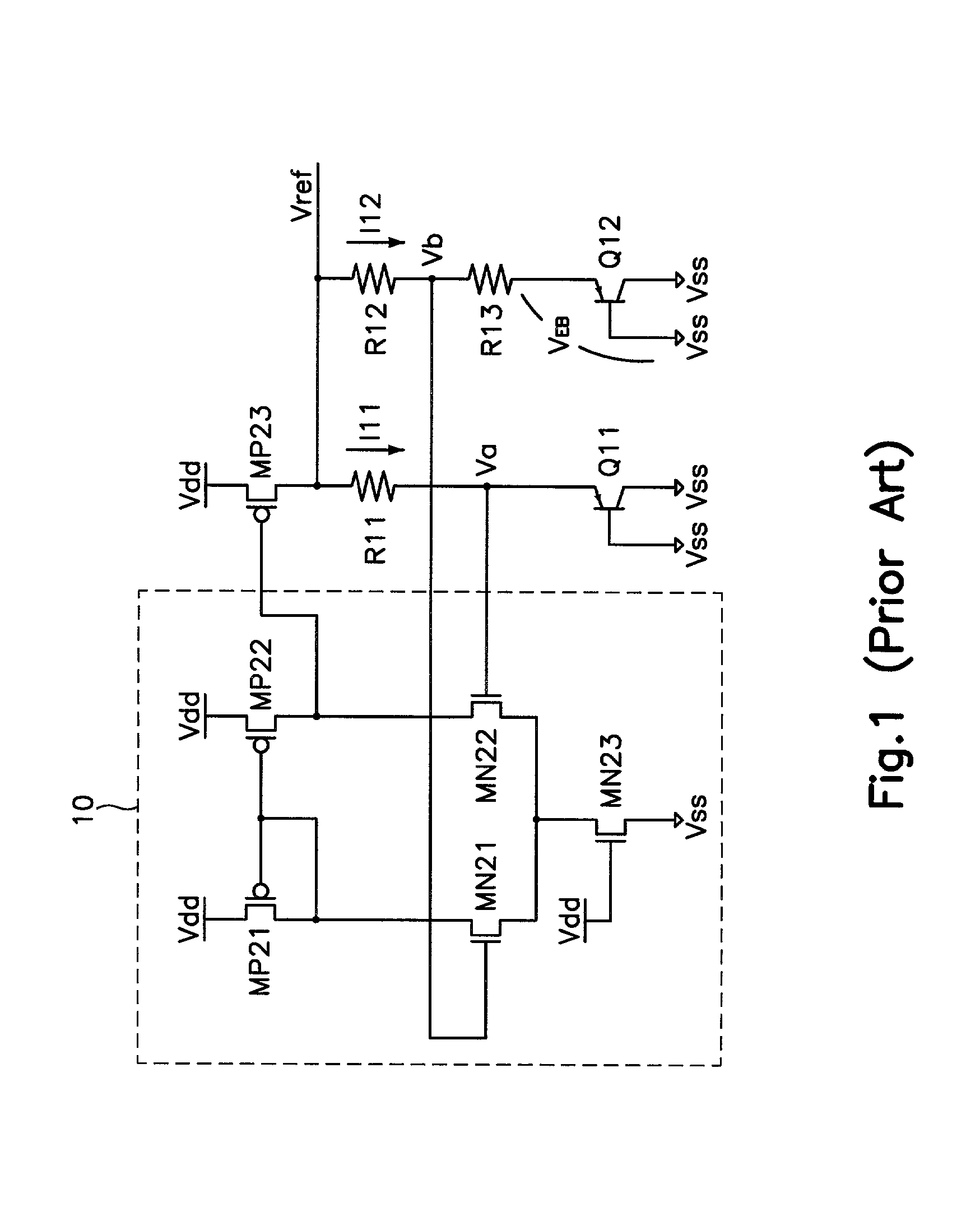
Accordingly, when the power voltage VDD, the temperature and the threshold voltage of the MOS transistor are varied, the conventional reference voltage generator is not normally operated, thereby causing a mis-operation.
In addition, the conventional bandgap reference voltage generator using the differential amplifier has a minimum operation voltage VDDmin over 1.4 V. Thus, it is not suitable for the DRAM having a low voltage tendency.
Although not illustrated, the conventional reference voltage generator has a disadvantage in that the reference voltage has a variation ratio of 0.44% in a period where the power voltage is 2.5 V and the temperature ranges from 20 to 90.degree. C., and has a high variation ratio of 0.91% in a period where the power voltage ranges from 2.25 V to 2.75 V and the temperature is 25.degree. C.
As a result, the conventional reference voltage generator cannot be relied upon to operate stably.

Method used


Image

  • Current mirror type bandgap reference voltage generator
  • Current mirror type bandgap reference voltage generator
  • Current mirror type bandgap reference voltage generator

Examples


Embodiment Construction

[0017] A current mirror type bandgap reference voltage generator in accordance with a preferred embodiment of the present invention will now be described in detail with reference to the accompanying drawings.

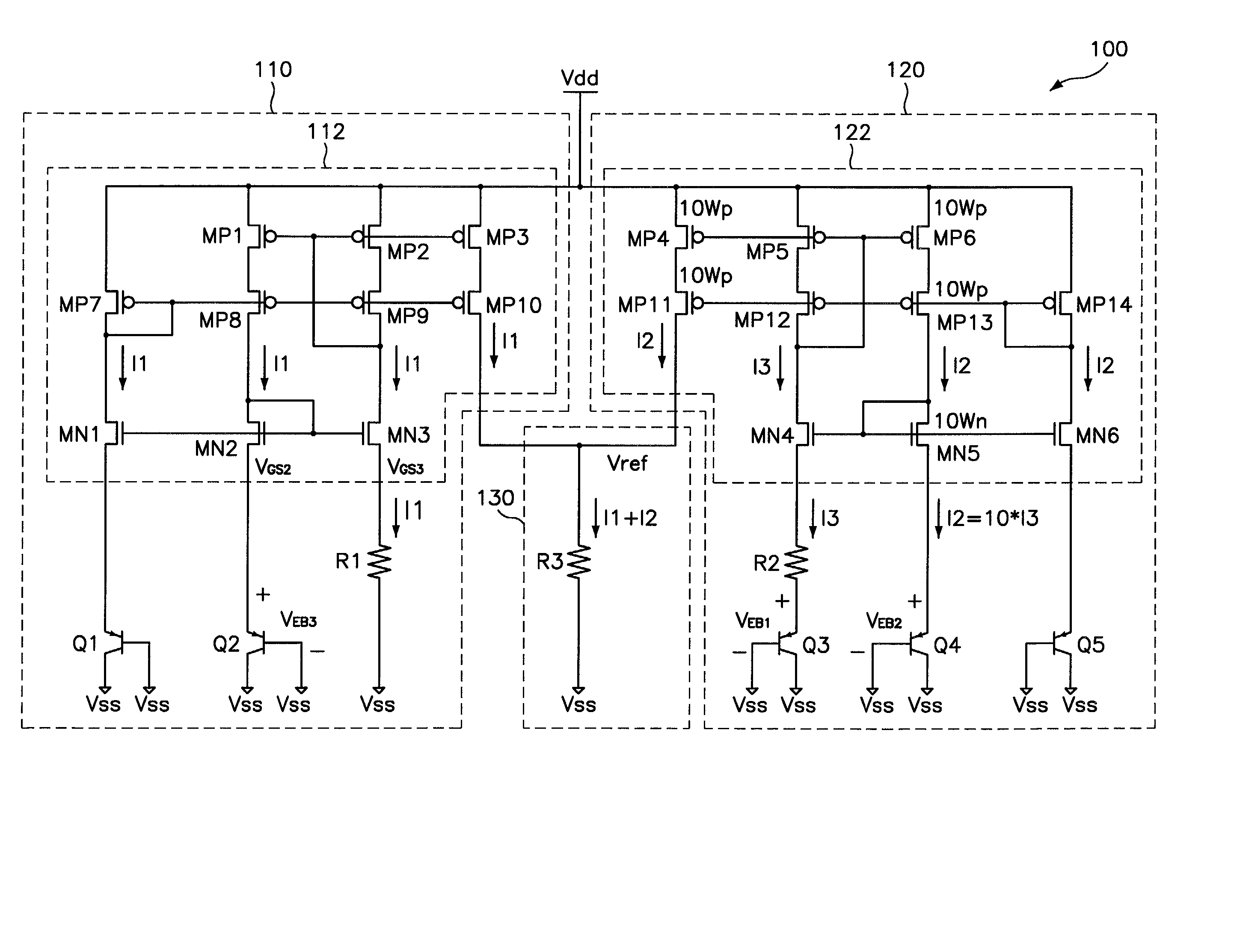
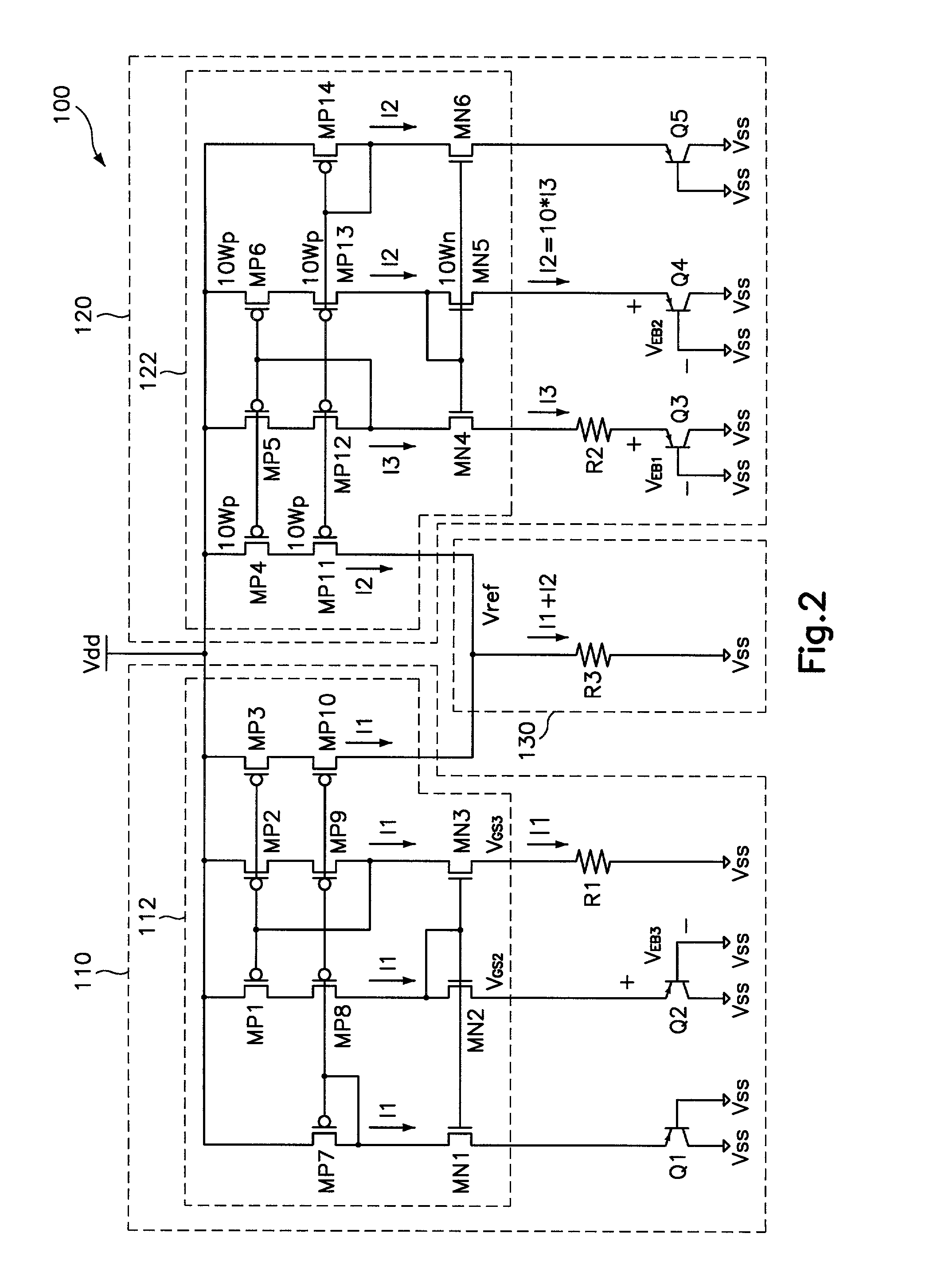
[0018] FIG. 2 is a circuit diagram illustrating the current mirror type bandgap reference voltage generator including a first current generator 110, a second current generator 120 and a reference voltage generator 130.

[0019] The first current generator 110 generates a first current I1 proportional to a base-emitter voltage V.sub.EB3 of a forwardly biased PNP type bipolar transistor Q2. The second current generator 120 generates a second current I2 proportional to a thermal voltage V.sub.T. The reference voltage generator 130 adds the first and second currents I1 and I2, and generates a constant reference voltage Vref regardless of variations of a temperature and a power voltage Vdd.

[0020] The first current generator 110 includes: a current mirror 112 for receiving the power volt...


PUM


Abstract

A current mirror type bandgap reference voltage generator which can reduce variations of a reference voltage due to temperature variations, by separately generating a current proportional to an emitter-base voltage and a current proportional to a thermal voltage, and which also can reduce variations of the reference voltage due to variations of a power voltage, by using a current mirror. The current mirror type bandgap reference voltage generator includes: a first current generator for generating a first current proportional to the emitter-base voltage; a second current generator for generating a second current proportional to the thermal voltage; and a reference voltage generator for adding the first and second currents, and generating a constant reference voltage regardless of variations of the temperature and the power voltage. As a result, the constant voltage is generated regardless of variations of the temperature and the power voltage.

Description

BACKGROUND OF THE INVENTION[0001] 1. Field of the Invention[0002] The present invention relates to a current mirror type bandgap reference voltage generator, and in particular to an improved current mirror type bandgap reference voltage generator which is suitable for generating a constant reference voltage regardless of variations in temperature and power voltage, by making use of a current mirror having a large output resistance and a large swing width.[0003] 2. Description of the Background Art[0004] In general, a reference voltage generator includes a reference voltage generator using a MOS transistor having a threshold voltage, and a bandgap reference voltage generator using a bipolar transistor. A CMOS bandgap reference voltage generator is discussed in IEEE Journal of Solid-State Circuit, Vol. 34, No. 5, May 1999, entitled by `A CMOS Bandgap Reference Circuit with Sub-1-V Operation`.[0005] In a conventional reference voltage generator, the reference voltage changes due to var...

Claims


Application Information

Patent Timeline
Patent Type & Authority Applications(United States)
IPC IPC(8): G05F3/26G05F3/30
CPCG05F3/267G05F3/30G05F3/26
Inventor KIM, YOUNG HEEJOO, JONG DOO
Owner SK HYNIX INC
Learn More