Acoustic wave touch actuated switch

a touch-actuated switch and acoustic wave technology, applied in the direction of electronic switching, pulse technique, instruments, etc., can solve the problems of metals and the like not being used, the type of switch is relatively expensive, and the switch type is expensive, and achieves the effect of simple circuitry

Inactive Publication Date: 2002-09-12
ILLINOIS TOOL WORKS INC
View PDF0 Cites 24 Cited by
  • Summary
  • Abstract
  • Description
  • Claims
  • Application Information

AI Technical Summary

Benefits of technology

0007] In accordance with the present invention, the disadvantages of prior switches as discussed above have been overcome. In accordance with the present invention, acoustic wave energy is substantially trapped in an acoustic cavity so as to provide an acoustic wave switch with a high Q. Because the Q of the switch is high, a touch can be detected with extremely simple circuitry.

Problems solved by technology

Further, the enclosure through which touch is sensed cannot be made of an electrically conducting material, so that metals and the like cannot be used.
This type of switch is expensive compared to a standard membrane switch and shares the disadvantages of membrane switches in that holes in the housing or enclosure are required to accommodate the switch.
This type of switch is relatively expensive and again requires openings in the housing or enclosure in which the switch is to be mounted.
As such, the ratio of the stored energy to lost or dissipated energy over a complete cycle, referred to as the Q of the switch, is inherently low and an extremely complex touch detection circuit is required to discriminate between a touch and the absence of a touch.
Moreover, the use of compressional waves in this switch is undesirable due to their sensitivity to liquids and other contaminants which can render the switch inoperable.
These systems are undesirable, however, because surface acoustic waves are sensitive to liquids and other contaminants that can render the panel inoperable.
Although this touch position sensor is insensitive to liquids and contaminants, touch position sensors that use reflective gratings or arrays and the associated touch detection circuitry are, in general, too expensive to use for an individual switch or for a small number of switches on a panel.

Method used


Image

  • Acoustic wave touch actuated switch
  • Acoustic wave touch actuated switch
  • Acoustic wave touch actuated switch

Examples


Embodiment Construction

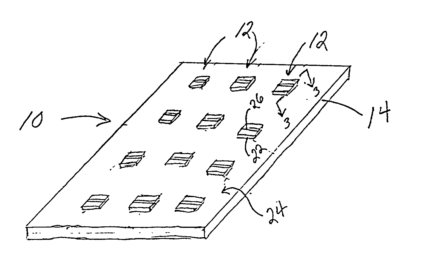
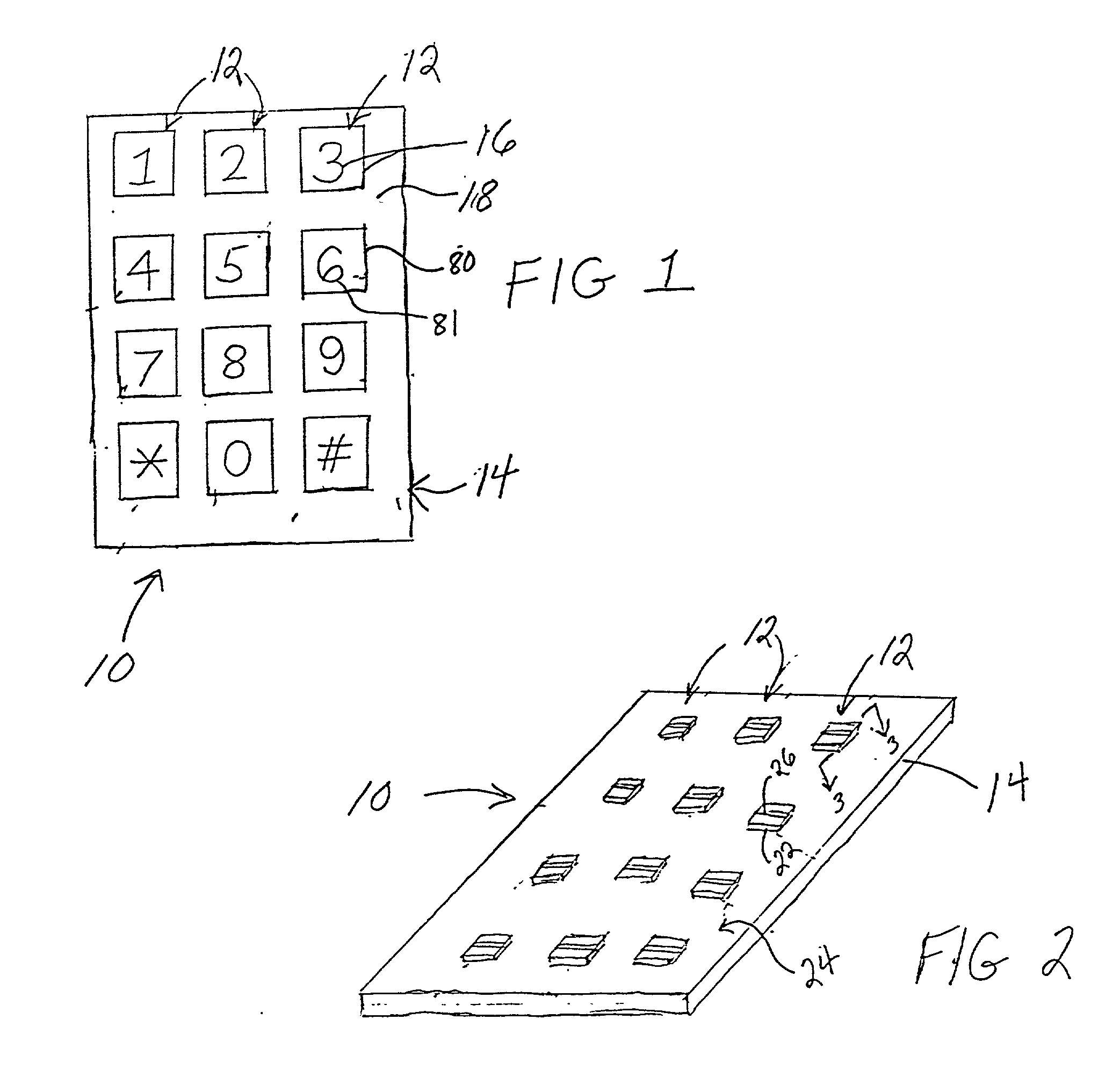
[0028] A touch panel 10 as shown in FIGS. 1 and 2 has a number of acoustic wave switches 12 in accordance with the present invention formed in the substrate 14 of the touch panel. Each acoustic wave switch 12 has respective indicia 16 formed on a top surface 18 of the panel. The indicia 16 identifies the position of a switch 12 and a switch actuation touch surface which are centrally located in the indicia 16. The indicia 16 can be formed in a number of different ways as described in detail below.

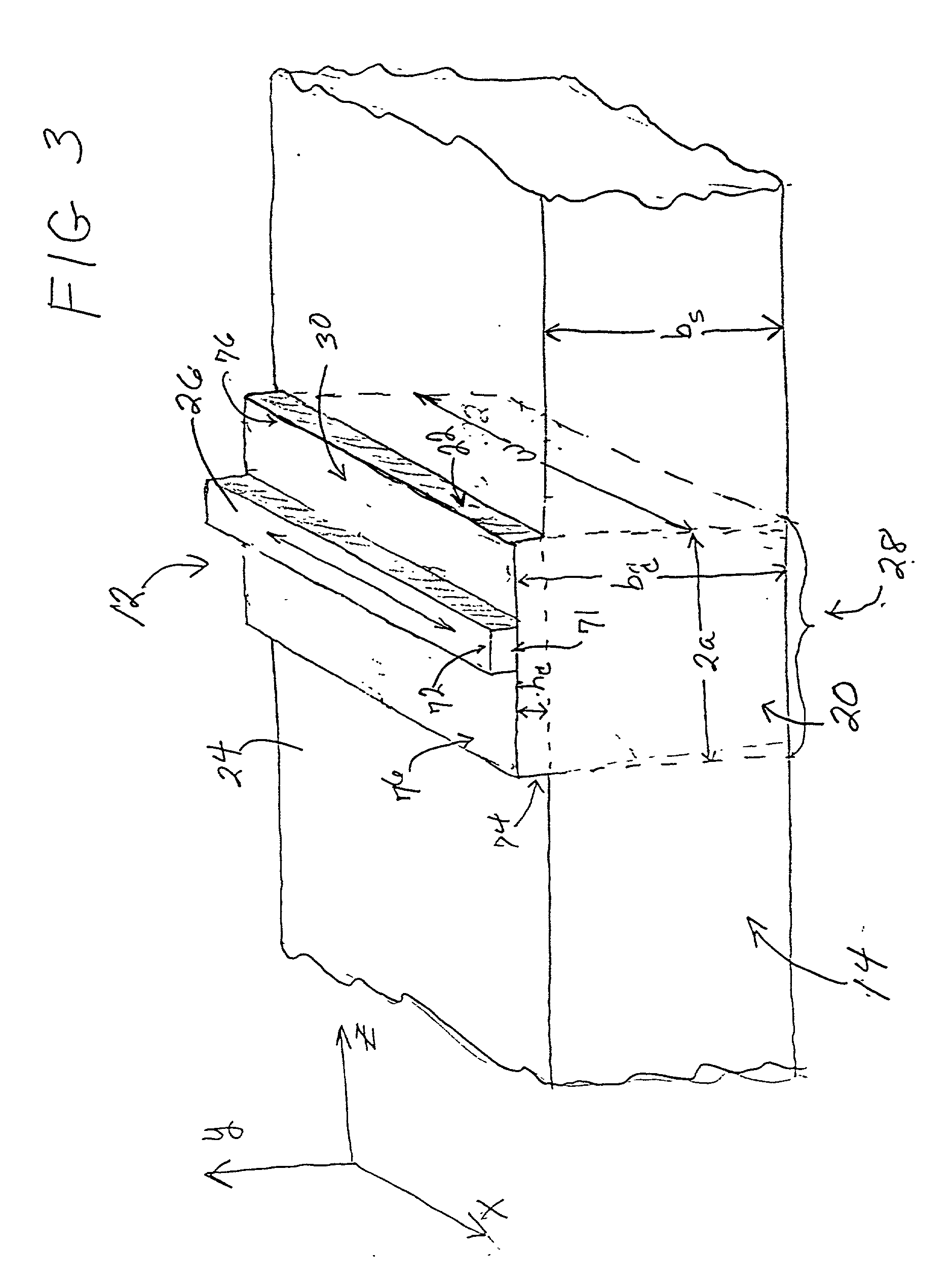
[0029] As shown in FIG. 2 and in more detail in FIG. 3, each acoustic wave switch 12 has an associated acoustic wave cavity 20 that extends through the thickness b.sub.s of the substrate 14. The acoustic wave cavity 20 is formed in the substrate 14 such that the mass per unit surface area of the acoustic wave cavity 20 is greater than the mass per unit surface area of the substrate adjacent the cavity. In one embodiment, the mass per unit area of the substrate in the switch region is increa...


PUM


Abstract

An acoustic wave switch includes a substrate with an acoustic wave cavity formed therein such that the mass per unit area of the acoustic cavity is greater than the mass per unit area of the substrate adjacent the cavity. A transducer is mounted on the acoustic cavity for generating an acoustic wave that is substantially trapped in the cavity. A touch on the touch surface of the acoustic wave cavity absorbs acoustic wave energy and produces a detectable change in the impedance of the transducer. The acoustic wave switch has a high Q so as to enable a touch to be detected by extremely simple, low-cost circuitry. The acoustic wave switch of the present invention is rugged, explosion proof, operates in the presence of liquids and other contaminants, has a low power consumption and can be incorporated and integrally formed in a wall of a housing for a device.

Description

CROSS-REFERENCE TO RELATED APPLICATIONS[0001] N / ASTATEMENT REGARDING FEDERALLY SPONSORED RESEARCH OR DEVELOPMENT[0002] N / AFIELD OF INVENTION[0003] The present invention relates to an acoustic wave touch actuated switch and more particularly to such a switch having an acoustic cavity that substantially traps acoustic wave energy so as to provide a high Q switch.BACKGROUND OF THE INVENTION[0004] There is a substantial need for finger touch actuated switches that are rugged and explosion proof, operate in the presence of liquids, have low power consumption, and are inexpensive. Known switches that attempt to meet these needs but fail include the following. A Qprox switch made by Quantum Research Group senses the presence of touch through a charge transfer effect. This switch is sensitive to conductive fluids and / or an ionizing atmosphere and can be made inoperable thereby. Further, the enclosure through which touch is sensed cannot be made of an electrically conducting material, so tha...

Claims


Application Information

Patent Timeline
Patent Type & Authority Applications(United States)
IPC IPC(8): H03K17/96
CPCH01H2239/054H03K17/96H03K2217/96011
Inventor KNOWLES, TERENCE J.BREMIGAN, CHARLES F. IIIKALMUS, CHRIS
Owner ILLINOIS TOOL WORKS INC
Why Eureka
Try Eureka