
Display panel module of low electromagnetic radiation

a display panel module and low electromagnetic radiation technology, applied in non-linear optics, identification means, instruments, etc., can solve the problem of affecting the electrically conductive frame of the display panel modul

Inactive Publication Date: 2002-09-12
FUJITSU LTD
View PDF22 Cites 62 Cited by
  • Summary
  • Abstract
  • Description
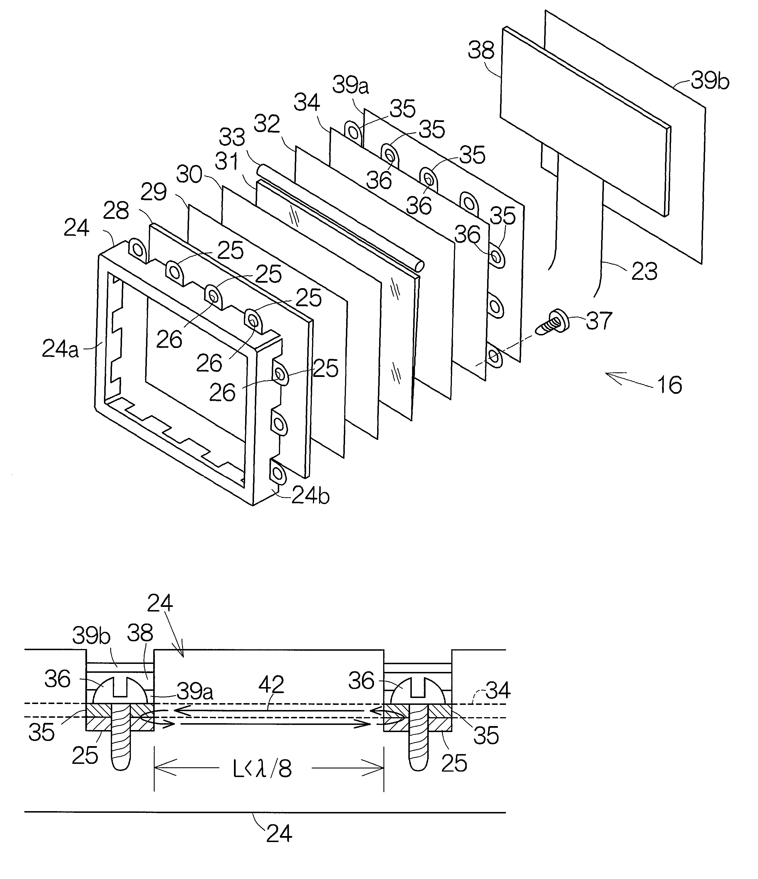
  • Claims
  • Application Information

AI Technical Summary

Benefits of technology

[0006] It is accordingly an object of the present invention to provide a display panel module capable of suppressing the radiation of electromagnetic waves in an efficient manner as compared with the aforementioned conventional shielding structure.
[0008] In general, a display panel module such as a liquid crystal display (LCD) panel module in an electronic apparatus is designed to receive a driving signal of a predetermined frequency. An electrically conductive frame of the display panel module tends to suffer from the transmission of electromagnetic waves which are related to the wavelength of the driving signal. The electrically conductive member connected to the electrically conductive frame serves to diverge the electromagnetic waves out of the electrically conductive frame. This divergence of the electromagnetic waves serves to suppress the electromagnetic radiation out of the electrically conductive frame.
[0009] The electrically conductive member is expected to cooperate with the electrically conductive frame so as to establish a loop line having a length different from the wavelength of the driving signal supplied to the display panel. The present inventors have found out an unknown fact that a larger quantity of the electromagnetic waves is radiated from the display panel module or LCD panel module, rather than a computer unit or main body enclosing a motherboard and the like, in a notebook personal computer, for example. The inventors have also discovered that an electrically conductive frame or bezel for binding the panel-shaped module components in the LCD panel module functions as a loop antenna. When electromagnetic waves are radiated from a circuit board in the LCD panel module on the basis of a driving signal for controlling the display on the screen of the LCD panel module, the driving signal of a predetermined wavelength tends to cause resonance of the electromagnetic waves with the bezel. The inventors have demonstrated this fact. The resonance is supposed to amplify the electromagnetic radiation out of the LCD panel module. If the length of the loop line is different from the wavelength of the driving signal, establishment of a loop antenna can be avoided in the electrically conductive frame. The electromagnetic radiation can thus be suppressed.

Problems solved by technology

An electrically conductive frame of the display panel module tends to suffer from the transmission of electromagnetic waves which are related to the wavelength of the driving signal.

Method used


Image

  • Display panel module of low electromagnetic radiation
  • Display panel module of low electromagnetic radiation
  • Display panel module of low electromagnetic radiation

Examples


Embodiment Construction

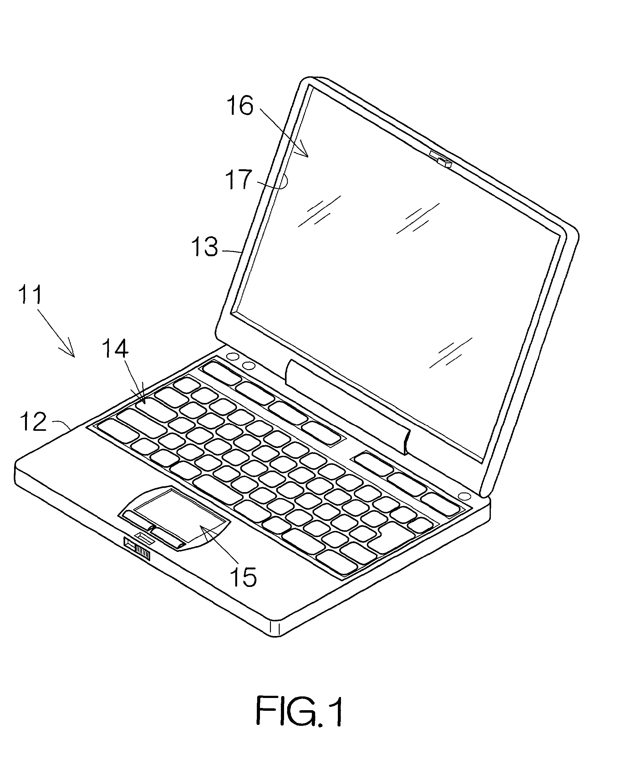
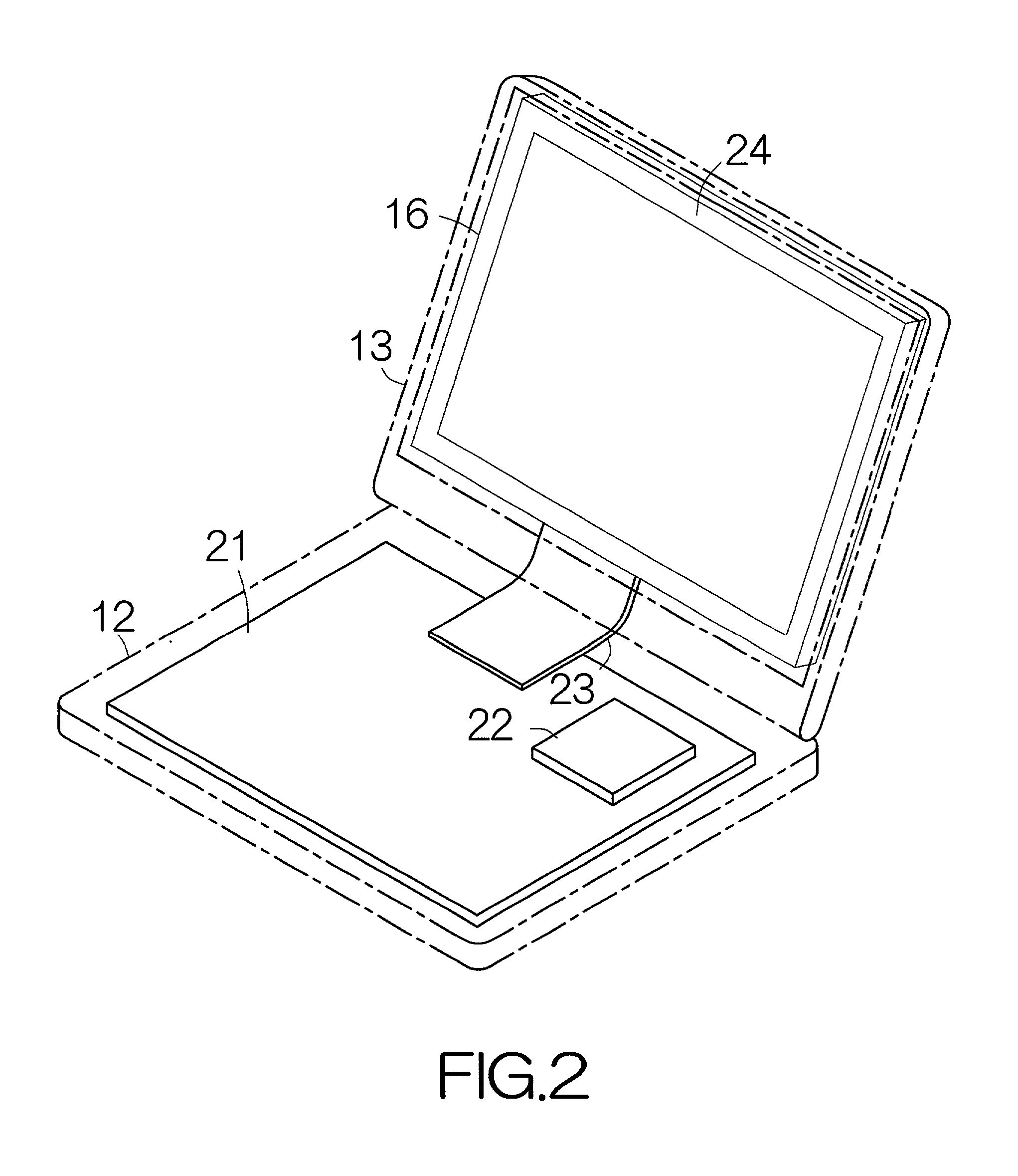
[0030] FIG. 1 schematically illustrates the exterior of a notebook personal computer. The notebook personal computer 11 comprises a computer unit or main body 12 of a reduced thickness and a display housing 13 coupled to the main body 12. The display housing 13 is allowed to pivot on the main body 12. Input devices such as a keyboard 14 and a pointing device 15 are embedded in the front or upper surface of the main body 12. A display panel module or liquid crystal display (LCD) panel module 16 is incorporated within the display housing 13. A screen of the LCD panel module 16 is exposed outside through a window 17 defined in the display housing 13. A user or operator is allowed to utilize the keyboard 14 as well as the pointing device 15 so as to manipulate the notebook personal computer 11. Moreover, the user is capable of observing the operation of the notebook personal computer 11 on the basis of text and / or graphics which appear on the screen of the LCD panel module 16, for examp...


PUM


Abstract

A display panel module such as a liquid crystal display (LCD) panel module in an electronic apparatus is designed to receive a driving signal of a predetermined frequency. An electrically conductive frame or bezel of the display panel module tends to suffer from the transmission of electromagnetic waves which are related to the wavelength of the driving signal. An electrically conductive member is located behind the display panel and electrically connected to the electrically conductive frame. The electrically conductive member serves to diverge the electromagnetic waves out of the electrically conductive frame. This divergence of the electromagnetic waves serves to suppress the electromagnetic radiation out of the electrically conductive frame.

Description

BACKGROUND OF THE INVENTION[0001] 1. Field of the Invention[0002] The present invention relates to a display panel module including a display panel such as a liquid crystal display (LCD) panel, for example.[0003] 2. Description of the Prior Art[0004] In general, a display panel module includes a circuit board for controlling the display of an image on a screen of a display panel assembled therein. The circuit board is designed to receive a driving signal from a CPU (Central Processing Unit), for example, of a computer system and the like. A display controller established on the circuit board controls the performance of individual liquid crystal cells on the basis of the supplied driving signal. The driving signal is synchronized with a predetermined clock signal. When the driving signal of a predetermined frequency is transmitted to the display controller, the circuit board tends to radiate electromagnetic waves.[0005] For example, Japanese Patent Application Laid-open No. 10-153766...

Claims


Application Information

Patent Timeline
IPC IPC(8): G02F1/13G09F9/00G02F1/1333
CPCG02F1/133308G02F2001/133334G02F1/133334
Inventor HIRATSUKA, YOSHIAKIYOSHINAGA, HISASHIYAMAGUCHI, MASANORI
Owner FUJITSU LTD
Learn More