EMI reduction in power modules through the use of integrated capacitors on the substrate level
Inactive Publication Date: 2002-09-12
CONTINENTAL AUTOMOTIVE SYST INC
View PDF0 Cites 26 Cited by
Summary
Abstract
Description
Claims
Application Information
AI Technical Summary
This helps you quickly interpret patents by identifying the three key elements:
Problems solved by technology
Method used
Benefits of technology
0013] The present invention provides high frequency, low impedance network for use in a power module for reducing radiated and conducted electromagnetic interference and the resulting noise and voltage overshoots. By "a high frequency, low impedance network" it is meant any structure characterized by an equivalent impedance below about 10 nanoHenry ("nH"), and typically between about 100 picoHenry and
Problems solved by technology
Current flowing through various inductive paths within the module transiently stores energy which increases energy loss, reduces efficiency, and generates heat.
When the flow of current changes, as in such a high frequency switching environment, large voltage overshoots often result, furthe
Method used
Image
Click on the blue label to locate the original text in one second.
Reading with bidirectional positioning of images and text.
Examples
Embodiment Construction
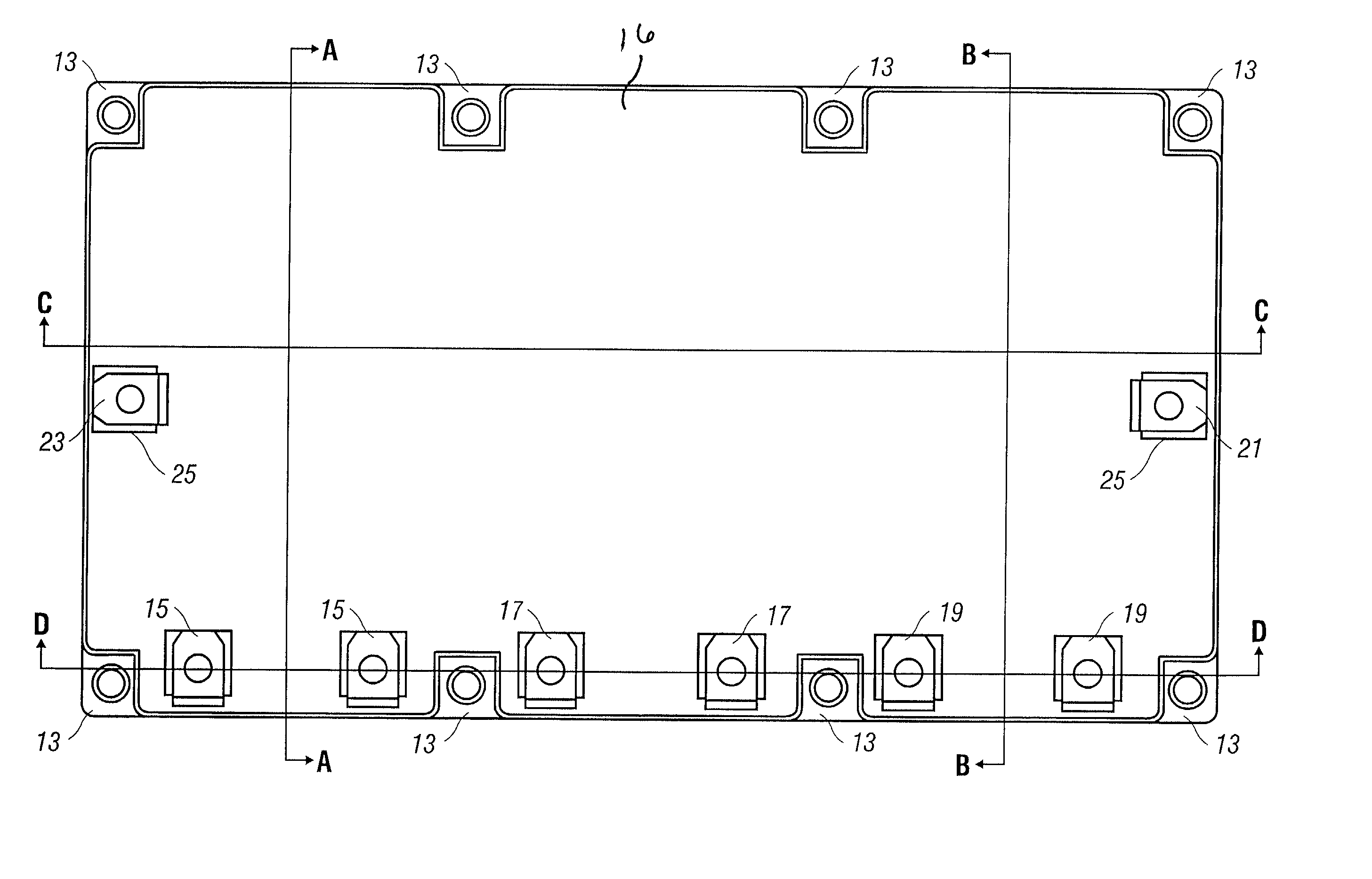
[0036] In accordance with the invention, a high frequency, low impedance network is used in a power module. The capacitance is shaped and positioned to minimize effects of electromagnetic interference and its associated voltage overshoots and noise. Reference is made herein to a power module with three phase terminals for use with a three-phase load, such as a three-phase motor, and having three half-bridges, each with one switching pair. As will be appreciated by one of ordinary skill in the art, the disclosed device, power module, DC bus, and method for reducing inductance in a power module could be used on a power module with any number of phase terminals and bridges, and having any number of switching pairs. Nonetheless, for ease of description, reference is made to a three-phase power module.
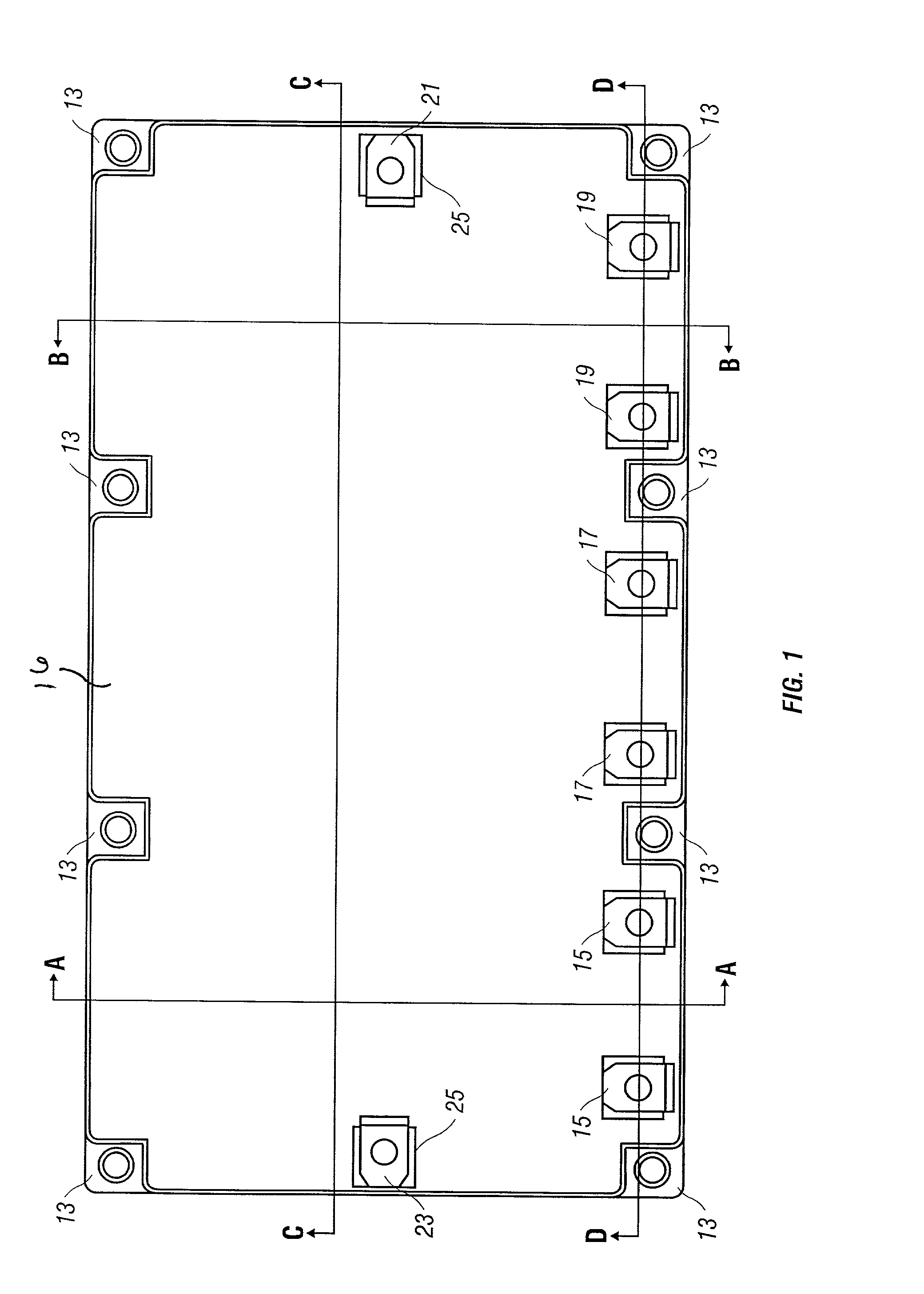
[0037] Referring to FIG. 1, an overhead view of the top of the power module is shown. The module has a positive lead 21 that is connectable to a power source, such as a battery, and a negat...
PUM
Abstract
A high frequency, low impedance network is integrated into the substrate level of a power module for the reduction of electromagnetic interference ("EMI"). In one embodiment, capacitance is electrically connected to at least one of the positive conducting layer in a substrate or the negative conducting layer in a substrate and a ground. Integrating a capacitive network of low stray inductance in a substrate of a power module allows relatively small, inexpensive capacitors to be used.
Description
CROSS REFERENCE TO RELATED APPLICATIONS[0001] This application is related to and claims priority to U.S. Provisional Application No. 60 / 233,995, filed Sep. 20, 2000, and entitled, "Leadframe-Based Module DC Bus Design to Reduce Module Inductance," U.S. Provisional Application No. 60 / 233,996, filed Sep. 20, 2000, and entitled, "Substrate-Level DC Bus Design to Reduce Module Inductance," U.S. Provisional Application No. 60 / 233,993, filed Sep. 20, 2000, and entitled, "EMI Reduction in Power Modules Through the Use of Integrated Capacitors on the Substrate Level," U.S. Provisional Application No. 60 / 233,992, filed Sep. 20, 2000, and entitled, "Press (Non-Soldered) Contacts for High Electrical Connections in Power Modules," and U.S. Provisional Application No. 60 / 233,994, filed Sep. 20, 2000, and entitled, "Both-Side Solderable Power Devices to Reduce Electrical Interconnects." Each of the above applications is hereby incorporated by reference herein in its entirety.BACKGROUND OF THE INV...
Claims
Application Information
Patent Timeline
Application Date:The date an application was filed.
Publication Date:The date a patent or application was officially published.
First Publication Date:The earliest publication date of a patent with the same application number.
Issue Date:Publication date of the patent grant document.
PCT Entry Date:The Entry date of PCT National Phase.
Estimated Expiry Date:The statutory expiry date of a patent right according to the Patent Law, and it is the longest term of protection that the patent right can achieve without the termination of the patent right due to other reasons(Term extension factor has been taken into account ).
Invalid Date:Actual expiry date is based on effective date or publication date of legal transaction data of invalid patent.