Dielectric waveguide with transverse index variation that support a zero group velocity mode at a non-zero longitudinal wavevector

a transverse index variation and waveguide technology, applied in the direction of instruments, cladded optical fibres, optical elements, etc., can solve the problem that the usefulness of waveguides in the optical regime (e.g., 350 nm to 3 microns) is limited by their absorption, so as to avoid the optical loss associated

Inactive Publication Date: 2002-09-12
MASSACHUSETTS INST OF TECH
View PDF5 Cites 14 Cited by
  • Summary
  • Abstract
  • Description
  • Claims
  • Application Information

AI Technical Summary

Benefits of technology

0006] The invention features a dielectric structure having a longitudinal axis, which supports an electromagnetic mode having a region where the group velocity passes from negative values to positive values over a range of non-zero longitudinal wavevector (i.e., it has a zero group velocity crossing). The presence of the mode having the zero group velocity crossing is caused by an index modulation perpendicular to the longitudinal axis. In other words, the zero group velocity mode can be present even when the dielectric structure has continuous translation symmetry along its longitudinal axis. Such symmetry is equivalent to the structure having a uniform cross-section. Notably, metallic regions are not necessary to produce the zero group velocity crossing, thus any component incorporating the structure may be all-dielectric, thereby avoiding the optical losses associated with metallic materials.

Problems solved by technology

Although metallic waveguides have a long history of use at longer wavelengths (e.g., microwaves), their usefulness as waveguides in the optical regime (e.g., 350 nm to 3 microns) is limited by their absorption.

Method used


Image

  • Dielectric waveguide with transverse index variation that support a zero group velocity mode at a non-zero longitudinal wavevector
  • Dielectric waveguide with transverse index variation that support a zero group velocity mode at a non-zero longitudinal wavevector
  • Dielectric waveguide with transverse index variation that support a zero group velocity mode at a non-zero longitudinal wavevector

Examples


Embodiment Construction

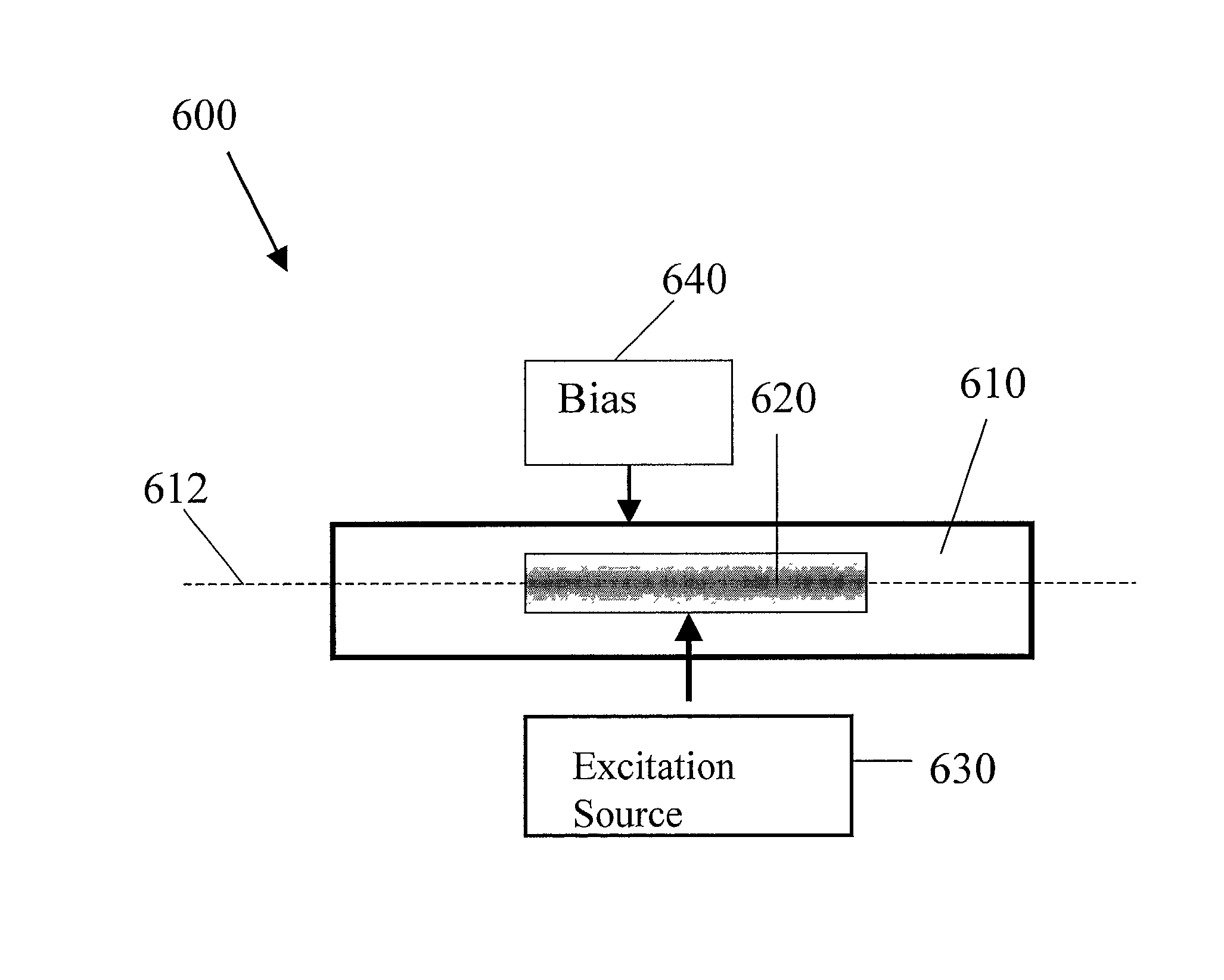
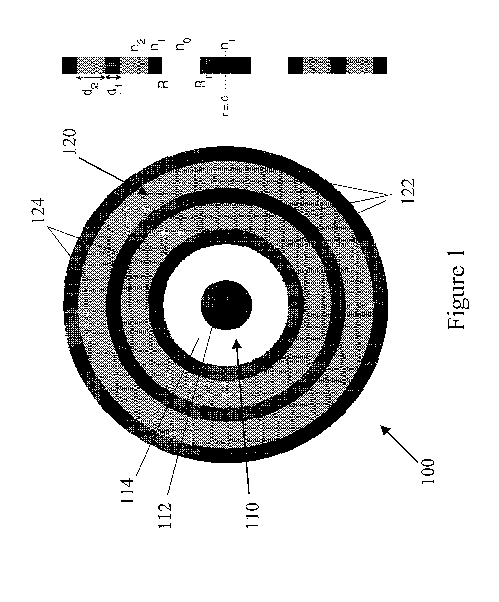
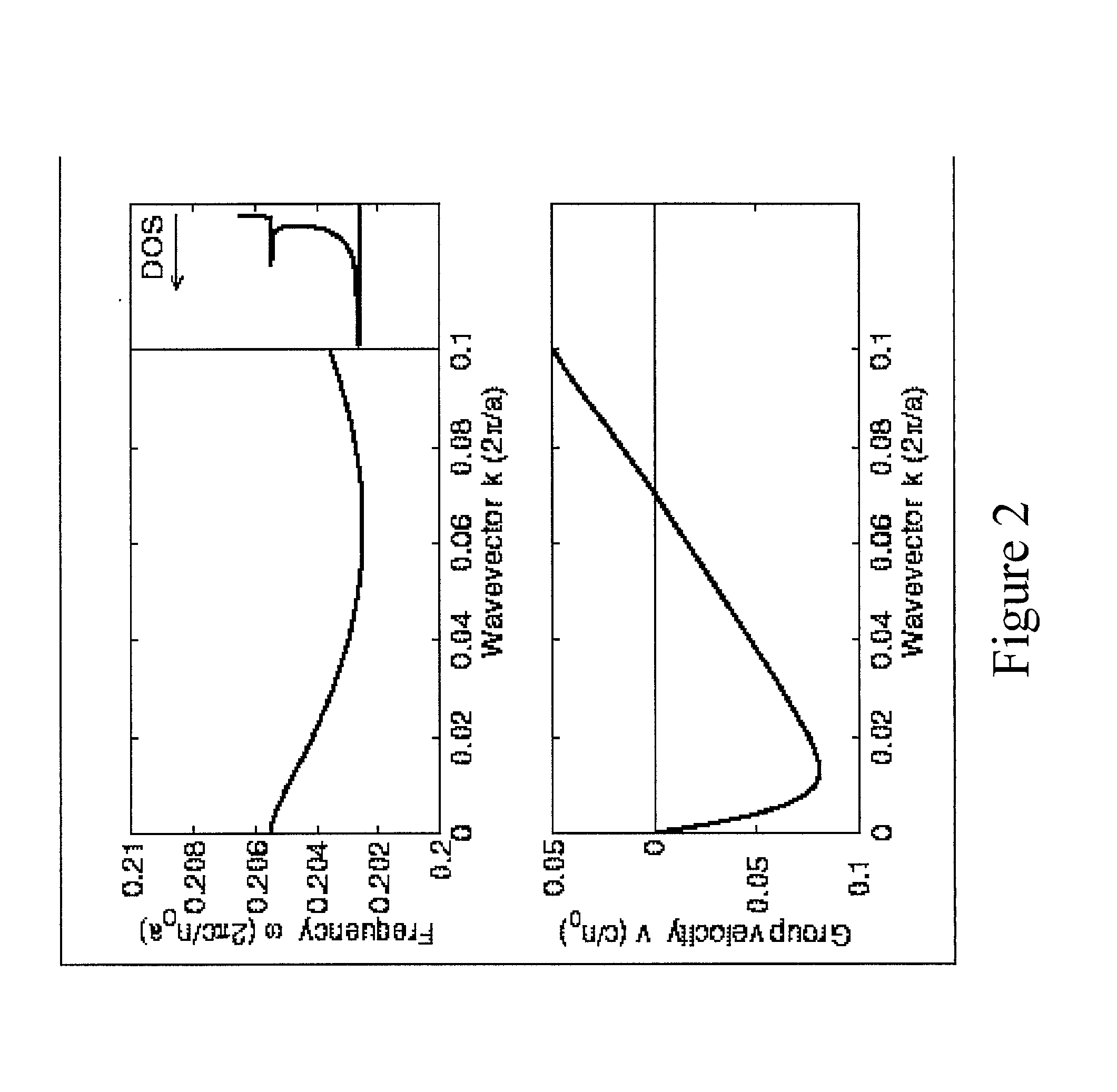
[0039] The invention relates to a dielectric structure having a longitudinal axis, such as a cylindrical dielectric waveguide 100, whose cross-section is shown in FIG. 1. Applicants have discovered that refractive index variations in the structure can be selected to cause it to support an electromagnetic (EM) mode that has a group velocity that changes sign over a range of non-zero wavevectors for the longitudinal axis.

[0040] Referring again to the particular embodiment shown in FIG. 1, waveguide 100 includes an inner region 110 and an outer region 120 surrounding the inner region. The refractive index variation in outer region 120 is selected to cause electromagnetic EM radiation propagating in inner region 110 to be substantially confined therein over at least one range of frequencies.

[0041] As shown in FIG. 1, for example, outer region 120 can be formed by an alternating series of concentric dielectric rings 122 and 124 having high (n.sub.1) and low (n.sub.2) indices of refractio...


PUM

PropertyMeasurementUnit
wavelengthsaaaaaaaaaa
refractive indexaaaaaaaaaa
group velocityaaaaaaaaaa

Abstract

Optical components including a laser based on a dielectric waveguide extending along a waveguide axis and having a refractive index cross-section perpendicular to the waveguide axis, the refractive index cross-section supporting an electromagnetic mode having a zero group velocity for a non-zero wavevector along the waveguide axis.

Description

CROSS-REFERENCE TO RELATED APPLICATIONS[0001] This application claims priority to U.S. provisional patent application 60 / 243,565 filed Oct. 26, 2000, the contents of which are incorporated herein by reference.BACKGROUND[0002] Optical components are becoming increasingly more common in telecommunication networks. For example, waveguides such as optical fibers are used to carry information between different locations as optical signals. Such waveguides substantially confine the optical signals to propagation along a preferred path or paths. Similarly, other components such as sources, modulators, and converters often include guided regions that confine electromagnetic (EM) energy. Although metallic waveguides have a long history of use at longer wavelengths (e.g., microwaves), their usefulness as waveguides in the optical regime (e.g., 350 nm to 3 microns) is limited by their absorption. Thus, dielectric waveguiding regions are preferred in many optical applications.[0003] One example...

Claims


Application Information

Patent Timeline
Patent Type & Authority Applications(United States)
IPC IPC(8): G02B6/02G02B6/028G02B6/036G02F1/01H01S3/063H01S3/067
CPCG02B6/02261G02B6/023G02F1/01G02F2202/32H01S3/063H01S3/06708G02F1/353
Inventor IBANESCU, MIHAIJOANNOPOULOS, JOHN D.FINK, YOELJOHNSON, STEVEN G.FAN, SHANHUI
Owner MASSACHUSETTS INST OF TECH
Why Eureka
Try Eureka