Nuclear power station primary pump

a technology for nuclear power stations and primary pumps, applied in the direction of corrosion prevention, lighting and heating apparatus, reactor fuel elements, etc., to achieve the effect of reducing crack formation in seals

Inactive Publication Date: 2002-09-12
JEUMONT
View PDF0 Cites 9 Cited by
  • Summary
  • Abstract
  • Description
  • Claims
  • Application Information

AI Technical Summary

Benefits of technology

[0009] An object of the invention is to avoid those drawbacks by proposing a nuclear power station primary pump in which the distribution of temperatures at the labyrinth type lip seal between the hot water of the primary circuit and the cooled zone is modified in such a way as to reduce crack formation in the seal.

Problems solved by technology

The diffuser rim, and consequently also the labyrinth type seal, are both subjected to a large temperature gradient which encourages thermal fatigue cracks to form on the lips of the seal.

Method used


Image

  • Nuclear power station primary pump
  • Nuclear power station primary pump
  • Nuclear power station primary pump

Examples


Embodiment Construction

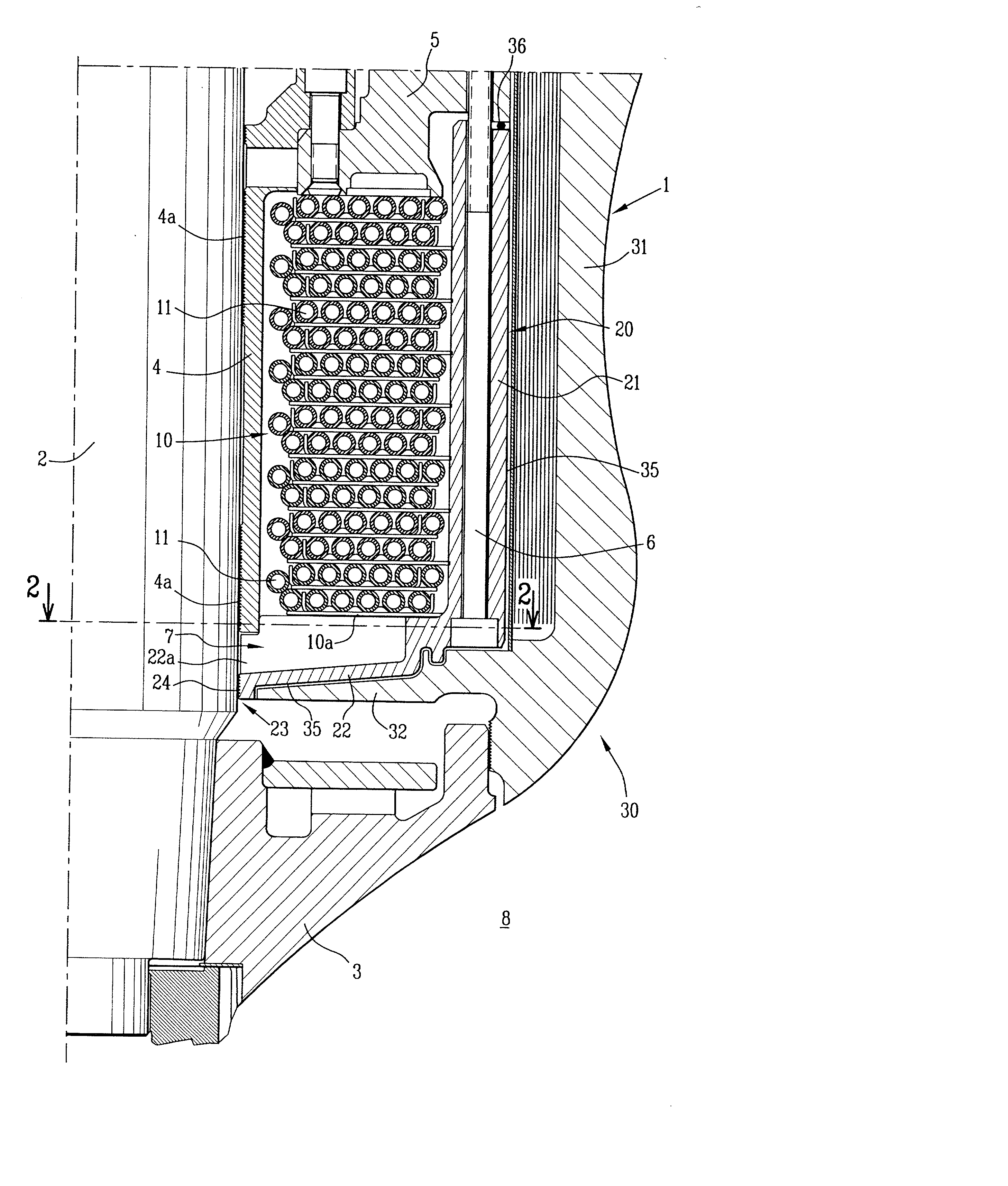
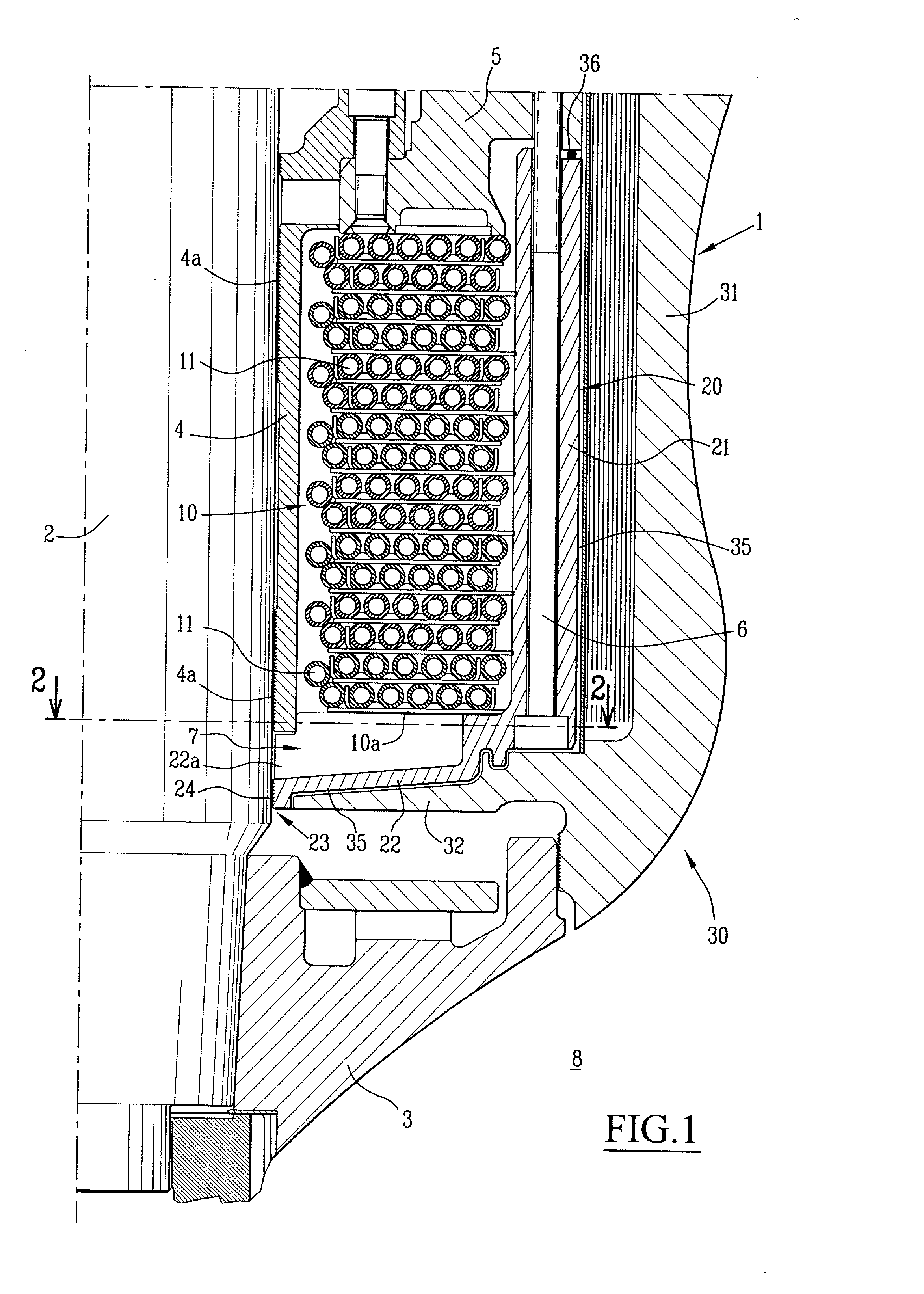
[0019] FIG. 1 is a diagram showing a portion of a primary pump in a nuclear power station, which pump is a single-stage pump of the helico-centrifugal type with vertical suction and horizontal delivery.

[0020] The pump is given overall reference 1 and comprises a drive shaft 2 for rotating a wheel 3 which is fixed by appropriate means to the base of said shaft 2. The pump 1 also comprises, above the wheel 3 and concentrically about the shaft 2, a heat exchanger 10 forming a thermal barrier, a thermal barrier cover 20, and a diffuser 30.

[0021] The heat exchanger 10 comprises a multitude of concentric tubes 11 distributed in superposed sheets, and a ring 4 is disposed between the shaft 2 and the heat exchanger 10.

[0022] On the inside, near its top and bottom portions, the ring 4 carries respective mechanical seals 4a of the labyrinth type.

[0023] The thermal barrier cover 20 is formed by a peripheral skirt 21 extending over the full height of the heat exchanger 10 and provided at its ba...


PUM


Abstract

The invention provides a nuclear power station primary pump of the type comprising a drive shaft for rotating a wheel, a heat exchanger, a thermal barrier cover comprising a peripheral skirt provided at its base with a circular end wall, and a diffuser comprising a peripheral skirt provided at its base with a rim. The circular end wall co-operates with the base of the heat exchanger to define a bottom chamber for cold water and includes a central bore provided with a succession of circumferential and superposed rings forming a lip seal of the labyrinth type, and a space is formed between the thermal barrier cover and the diffuser to maintain stagnant cooling fluid.

Description

[0001] The present invention relates to a nuclear power station primary pump.[0002] A primary pump in a nuclear power station comprises a drive shaft for rotating a wheel, and above said wheel and concentrically about said shaft, a heat exchanger forming a thermal barrier, a thermal barrier cover having a peripheral skirt provided at its base with a circular end wall extending beneath the heat exchanger, and a pump diffuser having a peripheral skirt concentric with said peripheral skirt of the thermal barrier cover and provided at its base with a rim extending beneath the circular end wall of said body.[0003] This type of primary pump also has a ring known as a "labyrinth" ring placed between the heat exchanger and the shaft, and a body having the heat exchanger and the peripheral skirt of the thermal barrier cover fixed thereto. This body is connected to the thermal barrier cover by link elements.[0004] Until now, the circular end wall of the thermal barrier cover has extended imme...

Claims


Application Information

Patent Timeline
IPC IPC(8): G21D1/04G21C15/243
CPCY02E30/40G21C15/243Y02E30/30Y02E30/00G21D1/04
Inventor MAZUY, LOUIS
Owner JEUMONT
Why Eureka
Try Eureka