
Electrochemical fuel cell with an electrode having an in-plane nonuniform structure

Inactive Publication Date: 2002-09-12
BALLARD POWER SYSTEMS
View PDF8 Cites 22 Cited by
  • Summary
  • Abstract
  • Description
  • Claims
  • Application Information

AI Technical Summary

Benefits of technology

0013] An improved electrochemic

Problems solved by technology

Other conditions are more likely to occur in certain portions of the reactant flow path in a fuel cell, for example, reactant starvation, overheating, drying, flooding.
If the reactant flow path across the electrode is tortuous, it may be more difficult to provide the desired variation in electrode properties directly along the flow path.

Method used


Image

  • Electrochemical fuel cell with an electrode having an in-plane nonuniform structure
  • Electrochemical fuel cell with an electrode having an in-plane nonuniform structure
  • Electrochemical fuel cell with an electrode having an in-plane nonuniform structure

Examples


Embodiment Construction

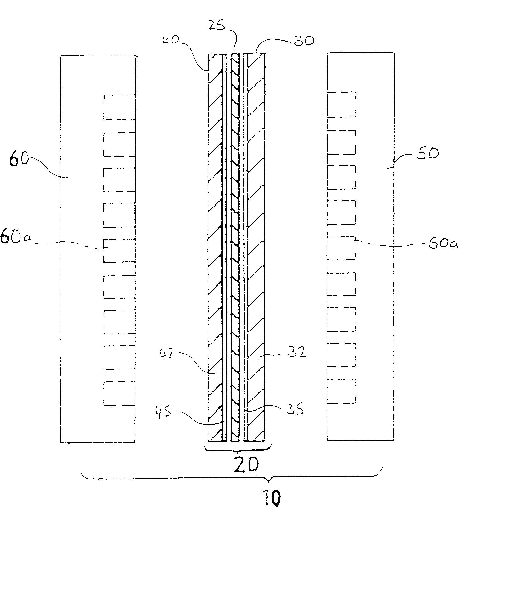
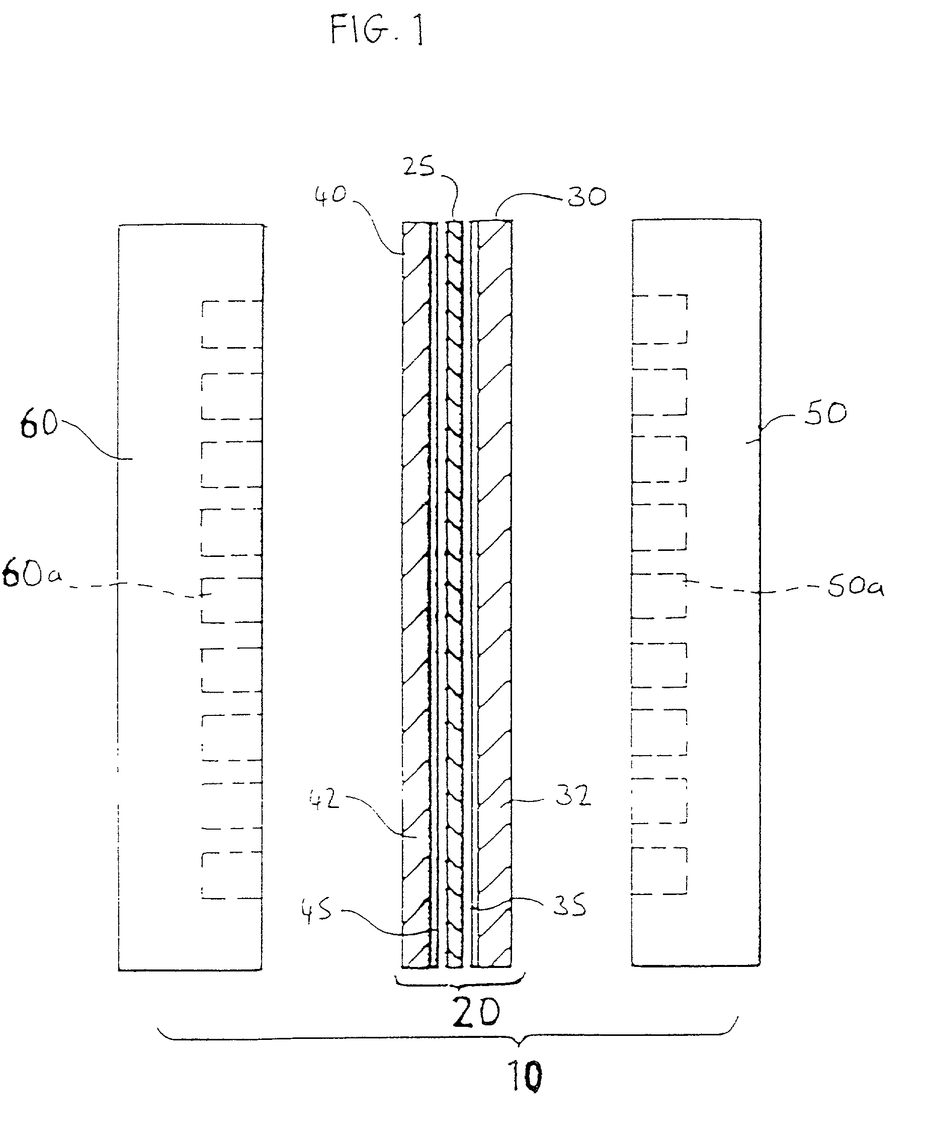
[0036] FIG. 1 illustrates a typical solid polymer fuel cell assembly 10. Fuel cell assembly 10 includes membrane electrode assembly 20 interposed between cathode flow field or separator plate 50 and anode flow field or separator plate 60. Membrane electrode assembly 20 comprises an ion exchange membrane 25 interposed between two electrodes, namely, cathode 30 and anode 40. In conventional fuel cells, cathode 30 and anode 40 comprise a substrate of porous electrically conductive sheet material 32 and 42, respectively, for example, carbon fiber paper or carbon cloth or a composite material. Substrates 32, 42 each have a pair of oppositely facing major planar surfaces. Each substrate has a thin layer of electrocatalyst 35 and 45, respectively, disposed on one of the major surfaces at the interface with membrane 25 to render each electrode electrochemically active.

[0037] As further shown in FIG. 1, cathode separator plate 50 has at least one oxidant stream flow channel 50a formed in the...


PUM


Abstract

In an improved electrochemical fuel cell assembly, a reactant flow path extends substantially linearly across the electrochemically active area of an electrode. The electrode has an in-plane nonuniform structure in its electrochemically active area as the active area is traversed in the direction of the substantially linear reactant flow path. Embodiments in which the structure of the fuel cell electrode varies substantially symmetrically along the reactant flow path are particularly preferred in fuel cells in which the flow direction of a reactant is periodically reversed.

Description

BACKGROUND OF THE INVENTION[0001] 1. Field of the Invention[0002] This invention relates generally to electrochemical fuel cells and, more particularly, to an electrochemical fuel cell assembly with an electrode having an in-plane nonuniform structure.[0003] 2. Description of the Related Art[0004] Electrochemical fuel cells convert fuel and oxidant to electricity and reaction product. Solid polymer electrochemical fuel cells generally employ a membrane electrode assembly ("MEA") comprising a solid polymer electrolyte or ion exchange membrane disposed between two electrodes. The electrodes typically each comprise a substrate formed principally of a porous, electrically conductive sheet material, such as, for example, carbon fiber paper, carbon cloth or a composite material. The electrodes also comprise an electrocatalyst, disposed at the membrane / electrode substrate interfaces in the MEA, to induce the desired electrochemical reaction. The location of the electrocatalyst generally de...

Claims


Application Information

Patent Timeline
IPC IPC(8): H01M4/86H01M4/96H01M8/02H01M8/04H01M8/24
CPCH01M4/8626H01M4/96H01M8/023H01M8/0241H01M8/2483H01M8/04156H01M8/241H01M2300/0082H01M8/0258Y02E60/50
Inventor WILKINSON, DAVID P.GIBB, PETER R.
Owner BALLARD POWER SYSTEMS
Learn More