Fuel cell and fuel cell stack

a fuel cell and stack technology, applied in the direction of cell components, cell component details, electrochemical generators, etc., can solve the problems of increasing manufacturing costs, unfavorable phenomena, and failure of sealing passages, so as to reduce the thickness of the fuel cell stack

Inactive Publication Date: 2002-09-12
HONDA MOTOR CO LTD
View PDF7 Cites 67 Cited by
  • Summary
  • Abstract
  • Description
  • Claims
  • Application Information

AI Technical Summary

Benefits of technology

0028] Since the thickness of the individual fuel cell is reduced as described above, the thickness of the fuel cell stack can be reduced b

Problems solved by technology

However, in such a sealing structure, a problem arises in that sealing of passages may fail if a pair of O-rings each disposed on both side of the solid polymer electrolyte member are insufficiently aligned.
In addition, an unfavorable phenomenon will be caused by deformation of the solid polymer electro

Method used


Image

  • Fuel cell and fuel cell stack
  • Fuel cell and fuel cell stack
  • Fuel cell and fuel cell stack

Examples


Embodiment Construction

[0047] Hereinafter, embodiments of the present invention will be described with reference to the attached drawings.

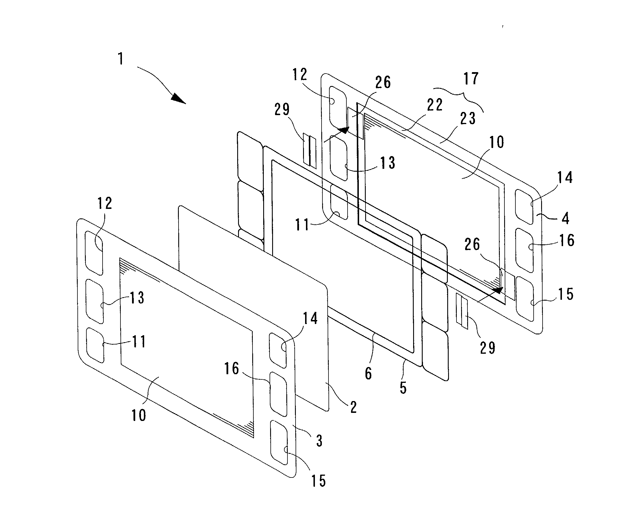
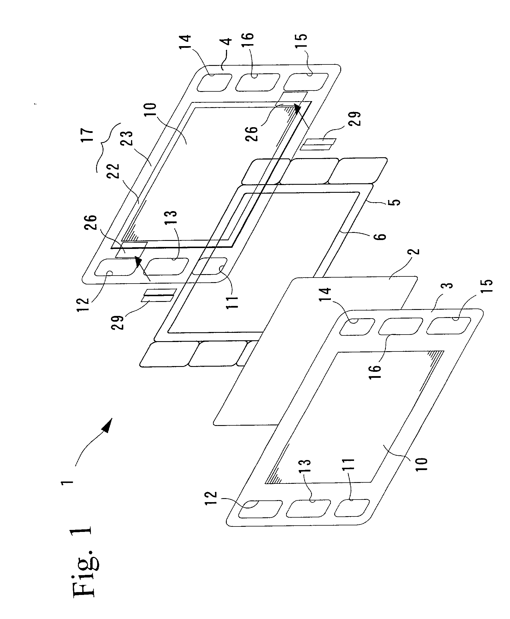
[0048] A fuel cell according to the present embodiment is, as shown in FIG. 1, constructed by sandwiching a membrane electrode assembly 2 with a pair of separators (first separator 3 and second separator 4), by tightly sealing the space between the first separator 3 and the second separator 4 with an outer peripheral sealing member 5 so as to surround the membrane electrode assembly 2, and by tightly sealing the space between the second separator 4 and the membrane electrode assembly 2 with an inner peripheral sealing member 6.

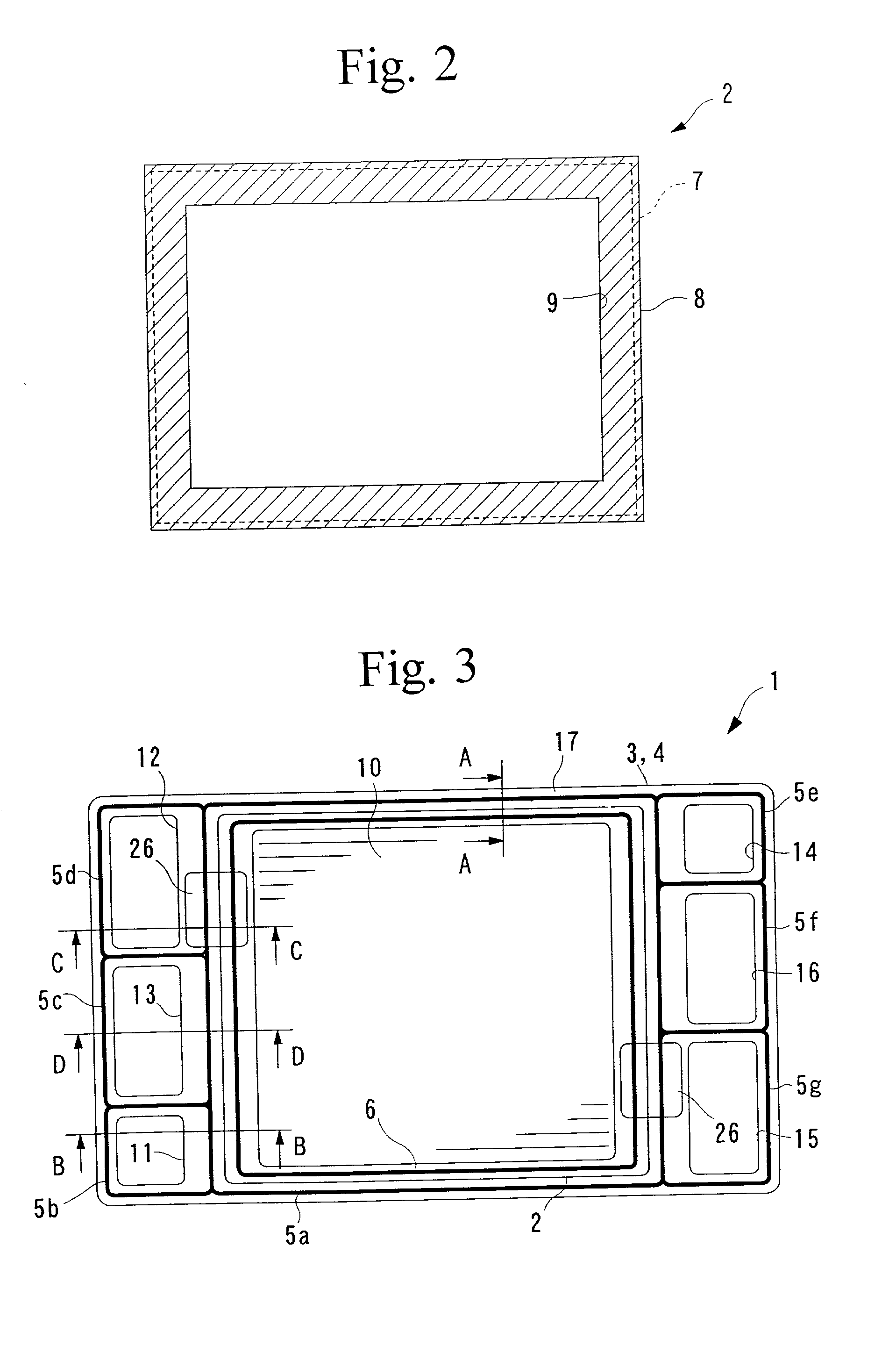
[0049] The aforementioned membrane electrode assembly comprises a solid polymer electrolyte membrane 8 (hereinafter, abbreviated as electrolyte membrane), made of a perfluorosulfonate polymer, and an anode electrode 7 and a cathode electrode 9, which sandwich both surfaces of the electrolyte membrane 8.

[0050] The anode electrode 7 and cathode elec...


PUM


Abstract

The present invention provides a fuel cell comprising a pair of separators sandwiching outsides of a membrane electrode assembly composed of a pair of electrodes provided on both sides of a solid polymer electrolyte membrane, an outer seal member sandwiched by a pair of separators at a position surrounding an outer periphery of the membrane electrode assembly, an inner seal member sandwiched by one of the pair of separators and an outer periphery of the electrolyte membrane, and a backing member opposing to the inner seal member interposing the electrolyte membrane, wherein steps are formed at contact surfaces of the inner seal member and the outer seal member on one of the pair of separators.

Description

BACKGROUND OF THE INVENTION[0001] 1. Field of the Invention[0002] The present invention relates to a solid polymer electrolyte membrane type fuel cell and to a fuel cell stack constituted by stacking a plurality of the fuel cell units, and more specifically, relates to a technique for absorbing expansion and contraction of the fuel cell stack in the stacking direction of separators.[0003] 2. Description of the Related Art[0004] Fuel cells include a solid polymer electrolyte membrane type fuel cell constituted by providing a pair of electrodes on opposite sides of the solid polymer electrolyte membrane and sandwiching the outside thereof by a pair of separators.[0005] In this fuel cell, a passage for a fuel gas (for example, hydrogen) is provided on the entire surface of a separator provided facing one electrode, a passage for an oxidant gas (for example, air including oxygen) is provided on the entire surface of a separator provided facing the other electrode, and a passage for a co...

Claims


Application Information

Patent Timeline
IPC IPC(8): H01M8/02H01M8/10H01M8/24
CPCH01M8/0271H01M8/241H01M8/2465H01M8/0273H01M8/2483H01M8/2457H01M8/242H01M2300/0082H01M8/0267Y02E60/50
Inventor SUGITA, NARUTOSHINAKANISHI, YOSHIHIROKUKUCHI, HIDEAKI
Owner HONDA MOTOR CO LTD
Why Eureka
Try Eureka