Since the purpose was to distribute television channels throughout a
community, the systems were designed to be one-way and did not have the capability to take information back from subscribers to the head end.
With the advent of these advanced services, there also arose numerous problems with using a physical CATV
plant designed to transmit video signals from town council meetings (using the forward path) to provide high-speed
Internet access for hundreds, if not thousands, of users simultaneously (using both the forward and return path).
Economically, the main problem that exists for CATV return path technology is that the return path signals need to be aggregated; which means the signals from many users are summed into a combined signal.
This equipment is so expensive that it cannot be cost justified today on the basis of
processing only one or even a couple of return signals.
Most HFC systems provide only a small number of optical fibers for each neighborhood, and thus these systems do not have enough optical fibers to provide a separate
optical fiber for each return signal.
Aggregation, when done by simply combining various RF level signals from the return signals of individual users, results in a degradation of the
signal to noise ratio (SNR) for the
system.
A problem known as "ingress" is often made much worse by the aggregation of many RF signals.
The
noise signals typically injected into the return paths of CATV systems are of unpredictable frequency and strength.
This is ingress and it can result in the loss of data for the other ninety-nine well-behaved users!
Analog
optical fiber return path links suffer from another problem.
The links degrade with distance and connector problems.
Connector and splice problems can cause a degradation in the
laser relative intensity noise (RIN), and all of these phenomena, including back scattering, cause light arriving at the receiver to have traveled different distances down the
fiber and hence some of the arriving light can be
out of phase with the transmitted RF signal.
Link degradation also can occur from the substantial temperature swings associated with the outdoor environment through which return path links travel, as well as rough handling of the return path link equipment by installers, for example during the installation of equipment at the top of poles.
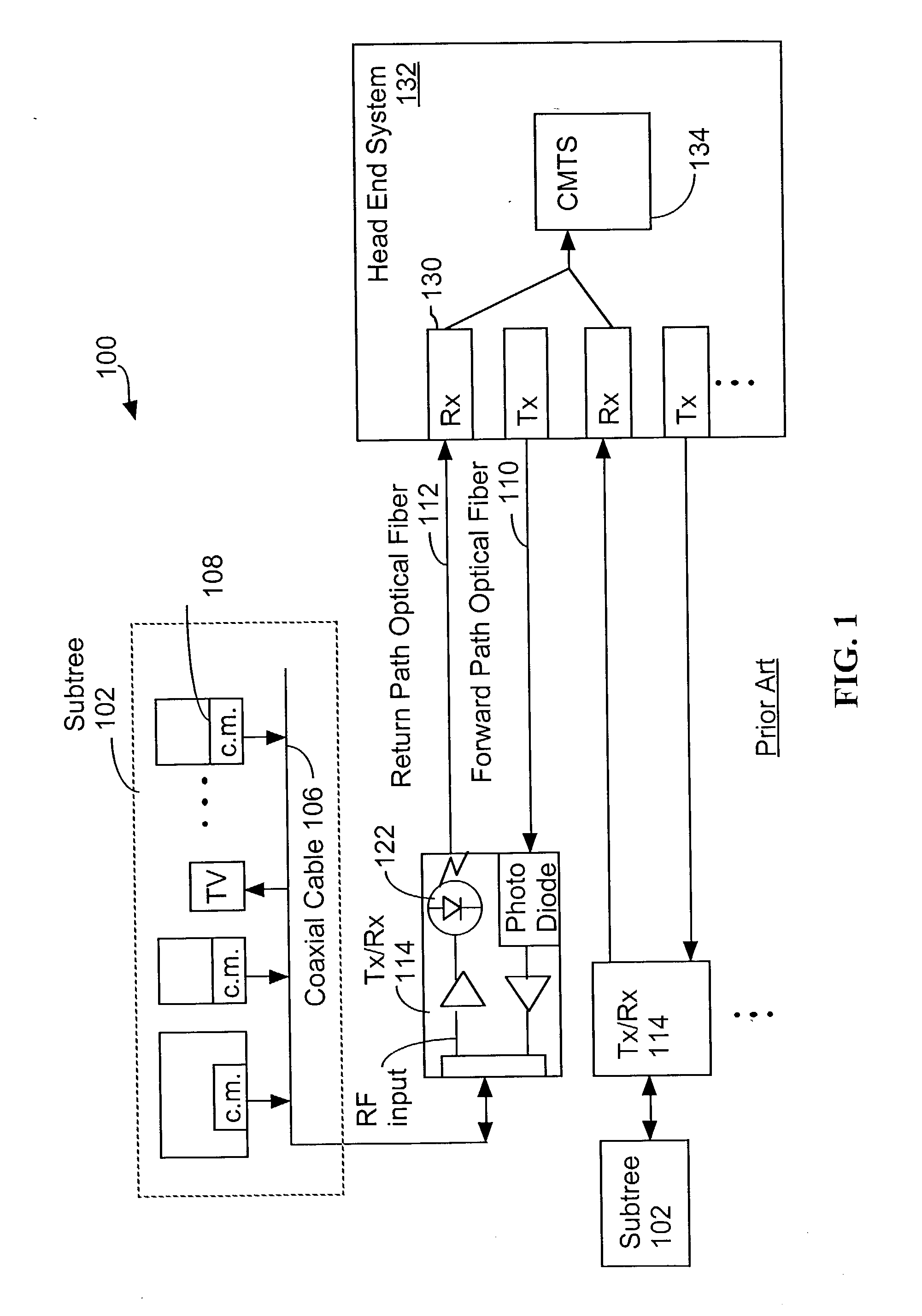
The system in FIG. 1 conforms generally to 1999 industry standards, and is susceptible to the ingress and link degradation problems described above.
DFB lasers are used in conjunction with an
optical isolator and have improved signal to
noise over FP lasers, but at a sacrifice of substantial cost.
Another shortcoming of the prior art return path link systems is inefficient use of the
fiber optic links.

