Method and system for stabilizing and demodulating an interferometer at quadrature

a quadrature and interferometer technology, applied in the field of interferometry, can solve the problems of difficult to maintain quadrature in practice, and achieve the effect of improving the stability and demodulation of the interferometer

Inactive Publication Date: 2002-09-19
TEXAS CHRISTIAN UNIVERSITY
View PDF0 Cites 8 Cited by
  • Summary
  • Abstract
  • Description
  • Claims
  • Application Information

AI Technical Summary

Benefits of technology

[0016] According to a preferred embodiment of the present invention, an interferometer control system receives from an interferometer a signal indicative of optical power of the interferometer. In response to receipt of the signal, the interferometer control system determines an optical path length correction required to stabilize the interferometer at quadrature utilizing signal amplitudes appearing at multiple harmonics of the signal. In a particularly preferred embodiment, the signal amplitudes are calculated utilizing the Goertzel algorithm, a computationally efficient discrete Fourier transform. The interferometer control system then outputs an error signal indicative of the optical path length correction. In a preferred embodiment, the error signal forms the DC component of a composite stabilization signal, whose AC component is the reference modulation signal utilized to excite a transducer to modulate the optical path length of the interferometer. With the interferometer stabilized at quadrature, the interferometer control system determines a first signal amplitude of a particular harmonic without target oscillation and a second signal amplitude of the same harmonic with target oscillation. Based upon the relative magnitudes of the first and second signal amplitudes, the interferometer control system determines a solution set for the displacement amplitude of the interferometer target. Any ambiguity in the displacement amplitude can then be eliminated utilizing additional information gained from the signal amplitude present at a harmonic of a target oscillation frequency.

Problems solved by technology

This condition, which is known as quadrature, is difficult to maintain in practice because vibrations and temperature and humidity-induced variations in k, the propagation constant, cause (D to drift from quadrature over time.

Method used


Image

  • Method and system for stabilizing and demodulating an interferometer at quadrature
  • Method and system for stabilizing and demodulating an interferometer at quadrature
  • Method and system for stabilizing and demodulating an interferometer at quadrature

Examples


Embodiment Construction

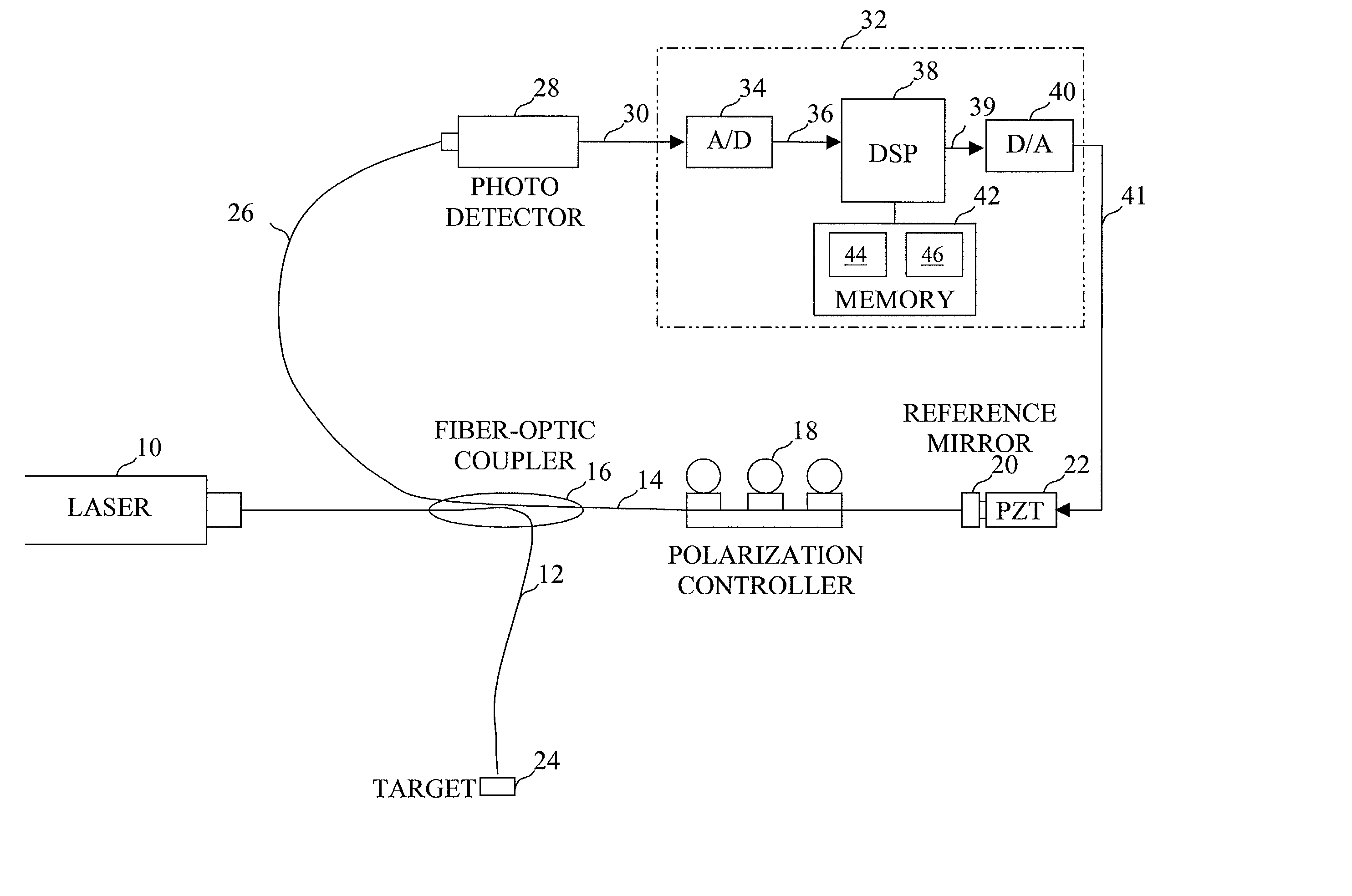
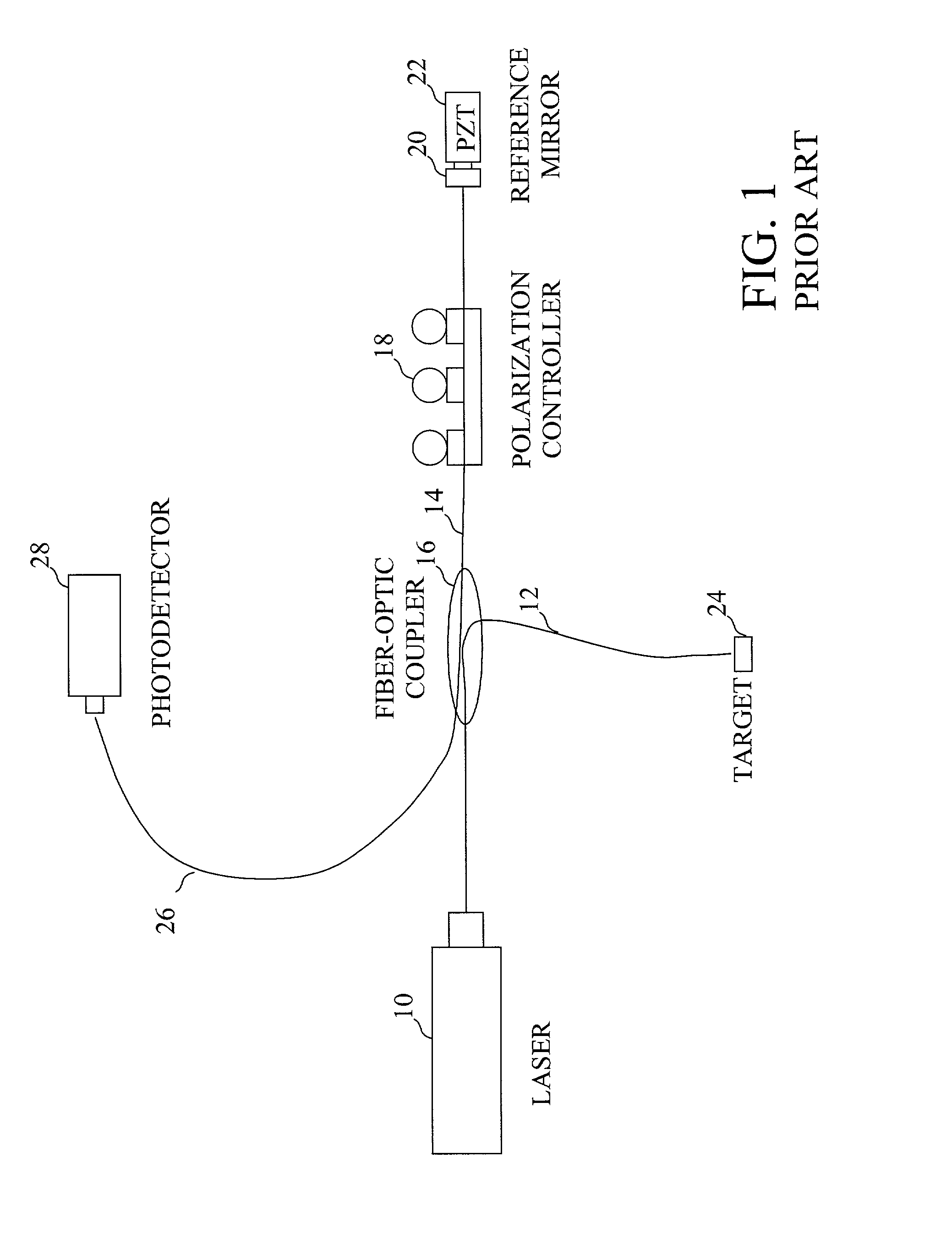
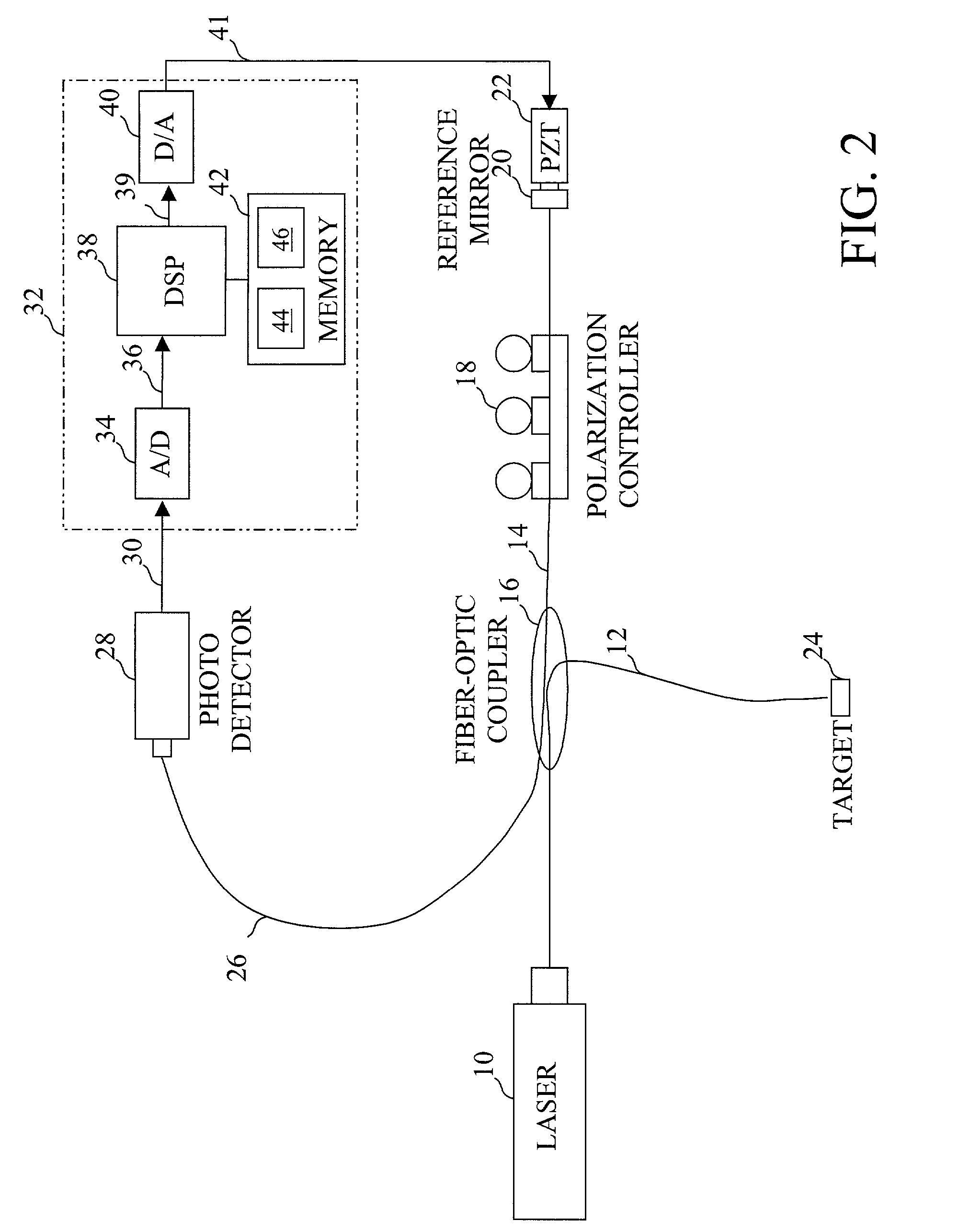
[0027] With reference again to the figures and in particular with reference to FIG. 2, there is illustrated a high-level block diagram of a Michelson configuration interferometer system that can be stabilized at quadrature in accordance with the present invention. In FIG. 2, like reference numerals are utilized to designate like and corresponding parts to the conventional interferometer illustrated in FIG. 1. The interferometer system shown in FIG. 1 is preferably a fractional fringe interferometer, meaning that the wavelength of the laser light produced by laser 10 is greater than the displacement of target 24.

[0028] As can be seen by comparison of FIGS. 1 and 2, the interferometer system depicted in FIG. 2 is like that illustrated in FIG. 1, the only difference being the addition of a DSP-based interferometer control system 32. Interferometer control system 32 includes an analog-to-digital (A / D) converter 34, digital-to-analog (D / A) converter 40, and a memory 42, all coupled to a ...


PUM


Abstract

A method and system for stabilizing and demodulating an interferometer at quadrature are described. In response to receipt of a signal indicative of optical power of the interferometer, an interferometer control system determines an optical path length correction required to stabilize the interferometer at quadrature utilizing signal amplitudes appearing at multiple harmonics of the signal. In a particularly preferred embodiment, the signal amplitudes are calculated utilizing the Goertzel algorithm, a computationally efficient discrete Fourier transform. The interferometer control system then outputs an error signal indicative of the optical path length correction. In a preferred embodiment, the error signal forms the DC component of a composite stabilization signal, whose AC component is the reference modulation signal utilized to excite a transducer to modulate the optical path length of the interferometer. With the interferometer stabilized at quadrature, the interferometer control system determines a first signal amplitude of a particular harmonic without target oscillation and a second signal amplitude of the same harmonic with target oscillation. Based upon the relative magnitudes of the first and second signal amplitudes, the interferometer control system determines a solution set for the displacement amplitude of the interferometer target. Any ambiguity in the displacement amplitude can then be eliminated utilizing additional information gained from the signal amplitude present at a harmonic of a target oscillation frequency.

Description

[0001] 1. Technical Field[0002] The present invention relates in general to interferometry and, in particular, to the stabilization and demodulation of an interferometer at quadrature.[0003] 2. Description of the Related Art[0004] An interferometer can be utilized to measure the small displacement amplitude of a vibrating target based upon the pattern formed by interfering two beams of light. Interferometry finds use, for example, in acoustic sensing, transducer calibration and microelectromechanical systems (MEMS) characterization.[0005] FIG. 1 illustrates a conventional fiber-optic interferometer in the Michelson configuration. As shown, laser light emitted from a He-Ne laser 10 is split into a signal arm beam 12 and a reference arm beam 14 by a fiber-optic coupler 16. Fiber-optic coupler 16 transmits reference arm beam 14 via fiber to a reference mirror 20, which reflects reference arm beam 14 back to fiber-optic coupler 16. Signal arm beam 12 is similarly transmitted via fiber t...

Claims


Application Information

Patent Timeline
IPC IPC(8): G01B9/02
CPCG01B9/02067G01B9/02084
Inventor TAYAG, TRISTAN J.BELK, CHRISTOPHER A.
Owner TEXAS CHRISTIAN UNIVERSITY
Why Eureka
Try Eureka