Optical fiber connector, ferrule used therefor and method for manufacturing ferrule

a technology of optical fiber connectors and ferrules, applied in the direction of electrolysis processes, instruments, electroforming processes, etc., can solve the problems of laborious polishing process, decreased productivity, and difficult to obtain a perfectly uniform inner diameter concerning

Inactive Publication Date: 2002-10-10
TETABUO TANAKA
View PDF13 Cites 40 Cited by
  • Summary
  • Abstract
  • Description
  • Claims
  • Application Information

AI Technical Summary

Problems solved by technology

However, the polishing process is laborious, and it requires skill, causing the decrease in productivity.
Further, it has been not easy to obtain a perfectly uniform inner diameter concerning the position in the axial direction of the inner hole of the fired product even when the polishing process is performed, for example, because the diamond is not uniformly attached to the linear polishing member.
Further, a problem arises in that the equipment cost is expensive, because the diamond-polishing member is consumed and exhausted.
A molding machine and a mold, which are expensive and specialized in this purpose, are required to perform the injection molding or the extrusion molding as described above.
Especially, the molding machine and the mold are conspicuously abraded by the extremely hard zirconia powder, and hence their service lives are short as well.
However, the production cost is extremely expensive for such a special molding machine and a special mold.
Further, the energy cost is increased, and the energy source is wasted as well, because the firing is performed at a high temperature of 500 to 1200.degree. C. in the firing step.
If the production cost of the ferrule is increased as described above, the production cost of an optical fiber connector including the ferrule accommodated therein is also increased.
Further, the following problem also arises.
In the case of the ferrules having two or more cores, it is extremely difficult to perform the step to establish the dimension by means of the polishing with the diamond-polishing member.
The production of ferrules having three or more cores has been substantially impossible.
The conventional ferrule made of zirconia or glass has involved the problem that such process cannot be easily performed.
A problem has been also pointed out in that the number of parts of the optical fiber connector is increased due to the use of such a holder.

Method used


Image

  • Optical fiber connector, ferrule used therefor and method for manufacturing ferrule
  • Optical fiber connector, ferrule used therefor and method for manufacturing ferrule
  • Optical fiber connector, ferrule used therefor and method for manufacturing ferrule

Examples


first embodiment

[0078] First Embodiment

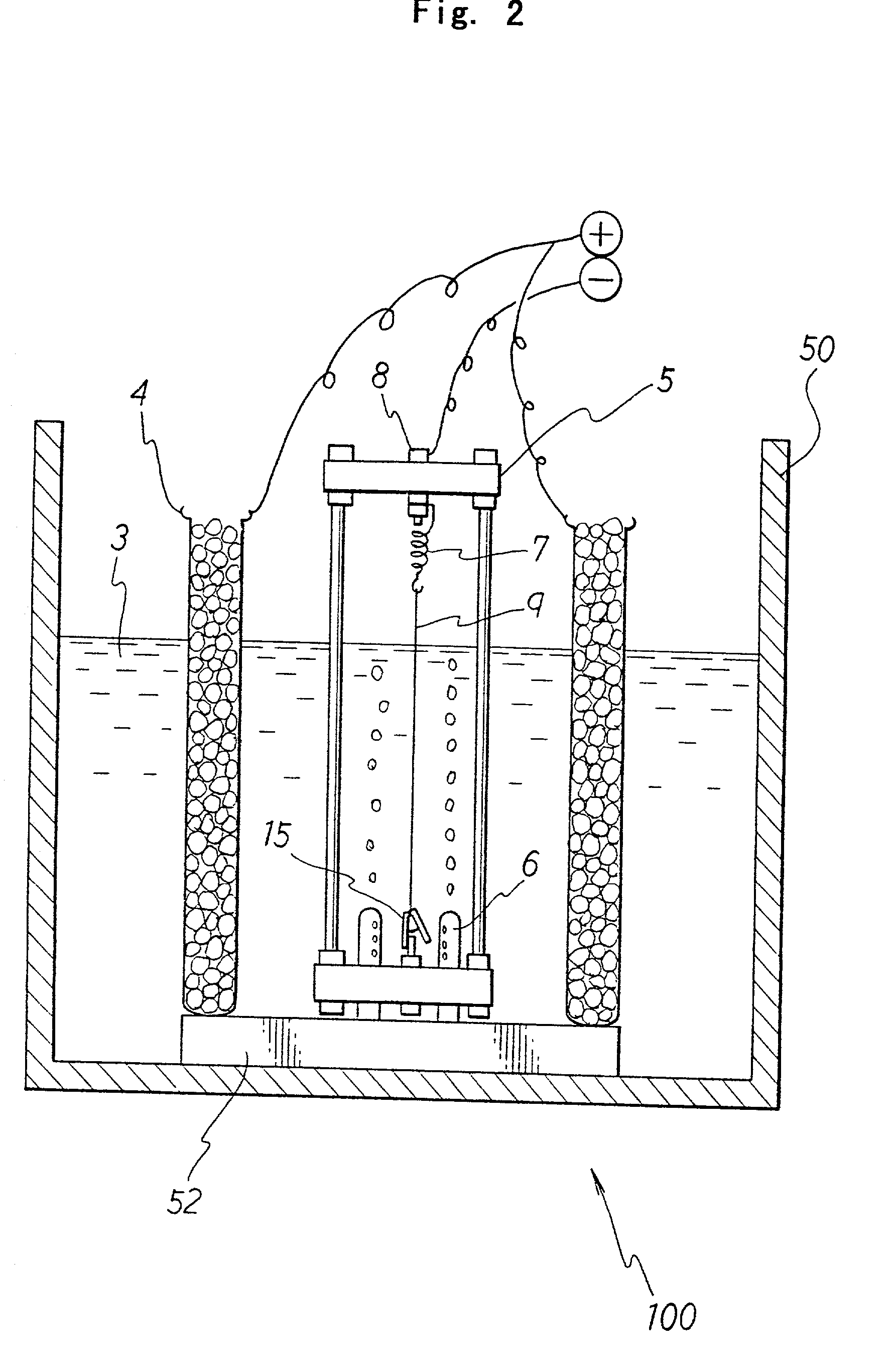
[0079] An aluminum alloy wire (alloy of copper, magnesium, and aluminum) of .phi.=0.126 mm having a circular cross section was prepared. The wire was set to the jig 5 in a state of being stretched in the vertical direction by means of the elasticity of the spring 7 as shown in (A) of FIG. 3. The surface of the alloy wire was degreased by sufficiently wiping the surface of the alloy wire with gauze immersed with petroleum benzine. An electroforming solution 3 containing a major component of nickel sulfamate was charged in the electroforming bath 50 shown in FIG. 2. The four anodes 4, which were composed of nickel balls placed in a net made of titanium enclosed in a polyester bag, were installed at the four corners of the base 52 around the center of the wire member 9. The electroforming bath was heated to obtain a temperature of 55.+-.5.degree. C. while performing high speed filtration at a filtration accuracy of 1 .mu.m. The jig 5 attached with the aluminum al...

second embodiment

[0081] Second Embodiment

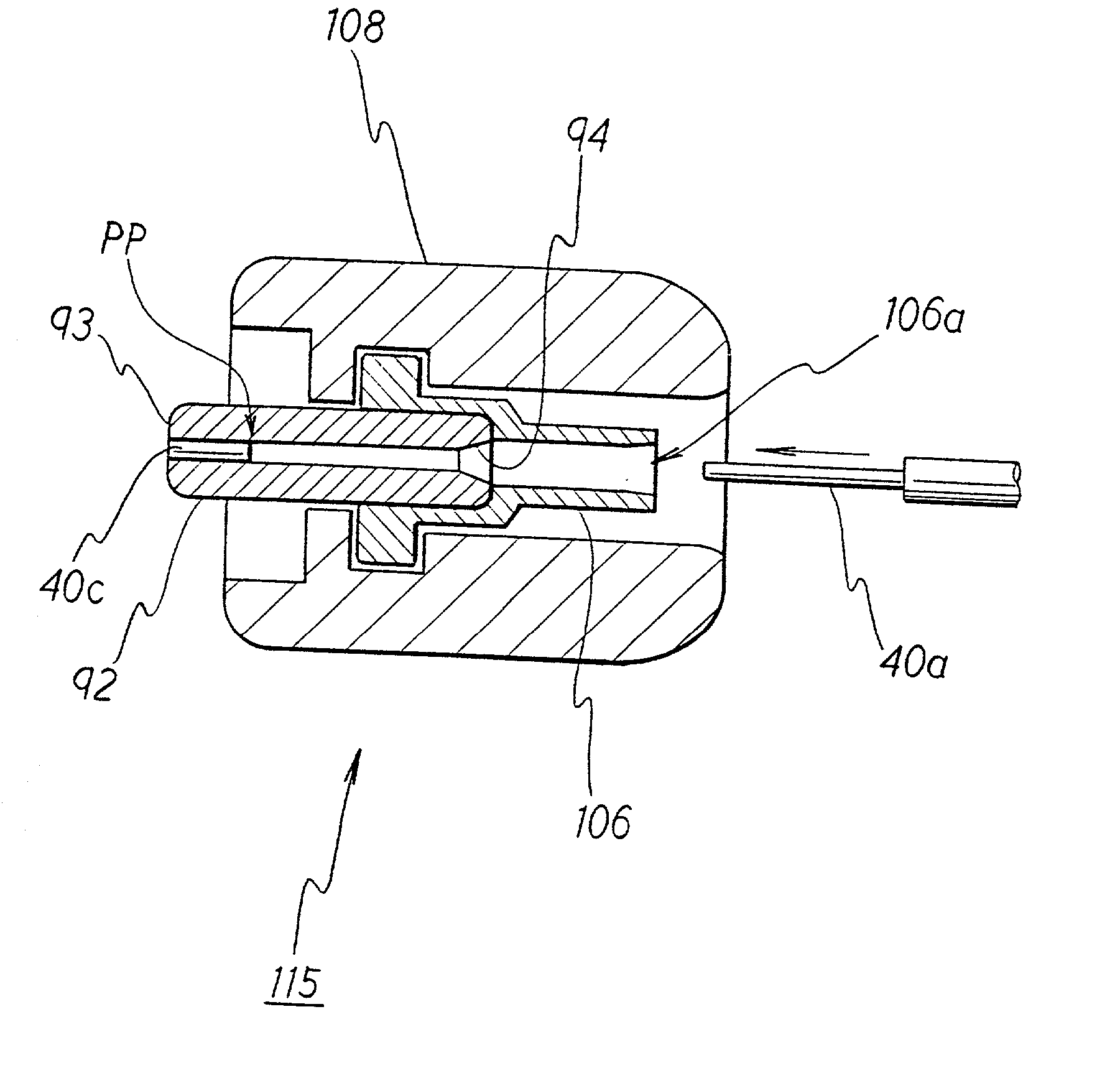
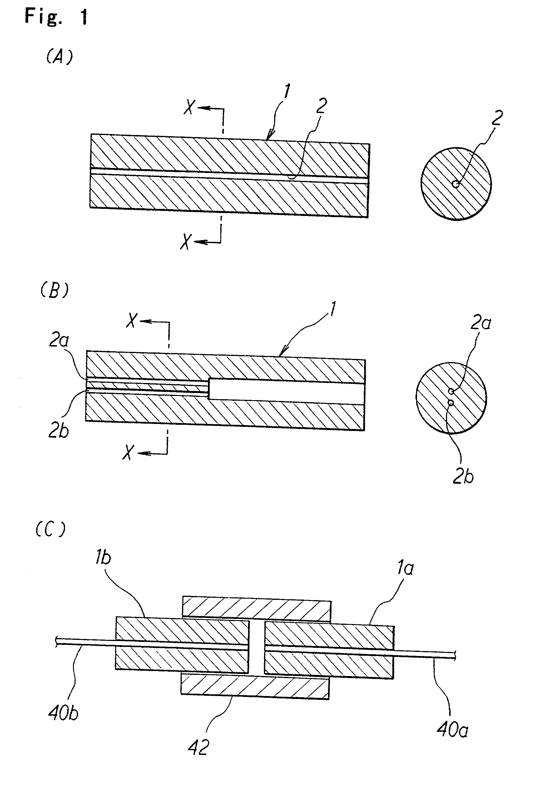
[0082] A wire member 9 composed of SUS 304 of .phi.=0.126 mm having a circular cross section was prepared, and the wire member 9 was set to the jig 5 in the same manner as in the first embodiment. As shown in FIG. 7, the wire member 9 was covered with a vinyl adhesive tape 20 at intervals of 40 mm. The jig 5 was washed with water, and then it was degreased and washed with water. After that, a mold release treatment was applied by immersing the wire member 9 at room temperature for 10 minutes in an aqueous solution of a mixture of commercially available Nikkanon Tack A, B produced by Nihon Kagaku Sangyo Co., Ltd. Subsequently, the wire member 9 was sufficiently washed with water, and then the electroforming was performed at 9 A / dm.sup.2 for one day in the same manner as in the first embodiment to obtain a nickel electroformed product having a thickness of .phi.=about 3 mm in average. The electroformed product was set to an extracting jig 24 formed with a throu...

third embodiment

[0083] Third Embodiment

[0084] An aluminum alloy wire having an elliptic cross section as shown in (A) of FIG. 5 was prepared. The aluminum alloy wire was an oval having a cross section with a minor axis of 0.126 mm and a major axis of 0.252 mm. The electroforming was performed with the aluminum alloy wire in the same manner as explained in the first embodiment. As a result, a two-core type ferrule was successfully obtained.


PUM

PropertyMeasurementUnit
diameteraaaaaaaaaa
lengthaaaaaaaaaa
temperatureaaaaaaaaaa

Abstract

Electroforming is performed in an electroforming bath with a cathode of a metal wire member immersed in an electroforming solution to electrodeposit nickel around the aluminum alloy wire member. The aluminum alloy wire member is removed by dissolution with an alkaline solution from an obtained nickel electroformed product. Accordingly, a nickel cylinder is obtained, which has a through-hole formed corresponding to the wire member. The cylinder is cut into those having a predetermined length. The outer circumference is subjected to cutting based on the through-hole to obtain a ferrule. The inner diameter accuracy of the through-hole of the ferrule is determined by the outer diameter accuracy of the wire member. Therefore, it is unnecessary to perform polishing for the through-hole. The highly accurate ferrule is obtained in accordance with the simple process at low cost. The PC polishing for the ferrule for effecting PC junction of optical fibers is extremely easy, because the ferrule is made of metal. Thus, it is possible to provide a high performance optical fiber connector.

Description

[0001] 1. Field of the Invention[0002] The present invention relates to an optical fiber connector, a ferrule to be used for the optical fiber connector, and a method for producing the ferrule. In particular, the present invention relates to an optical fiber connector for correctly aligning mutual positions of cores of optical fibers and connecting them to one another by inserting the optical fibers into cylindrical ferrules to support them, a ferrule to be used for the optical fiber connector, and a method for producing the ferrule. The present invention also relates to a wire member-supporting apparatus to be used for producing the ferrule.[0003] 2. Description of the Related Art[0004] In recent years, the electric cable for the telephone line is being replaced with the optical fiber cable on a worldwide scale. The use of the optical fiber is not limited to the optical communication based on the telephone. The optical fiber is also widely used for optical devices, apparatuses for ...

Claims


Application Information

Patent Timeline
Patent Type & Authority Applications(United States)
IPC IPC(8): C25D1/02G02B6/38G02B6/36
CPCC25D1/02G02B6/3807G02B6/3893G02B6/3833G02B6/3825G02B6/36
Inventor TANAKA, TETSUOOKAMOTO, SHINICHI
Owner TETABUO TANAKA
Why Eureka
Try Eureka