Paint dryer and paint dryer system

Inactive Publication Date: 2002-10-17
ABB FLAEKT AB
View PDF0 Cites 24 Cited by
  • Summary
  • Abstract
  • Description
  • Claims
  • Application Information

AI Technical Summary

Problems solved by technology

This approach involves, for one thing, additional costs and, for another, an increased space requirement whilst hampering access to the other ducts, conduits, filters and more particularly to the radiant pods of a paint dry

Method used


Image

  • Paint dryer and paint dryer system
  • Paint dryer and paint dryer system
  • Paint dryer and paint dryer system

Examples


Embodiment Construction

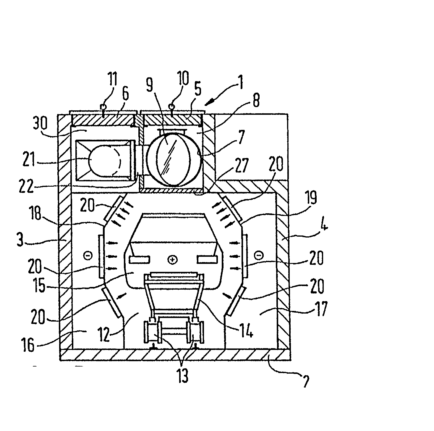
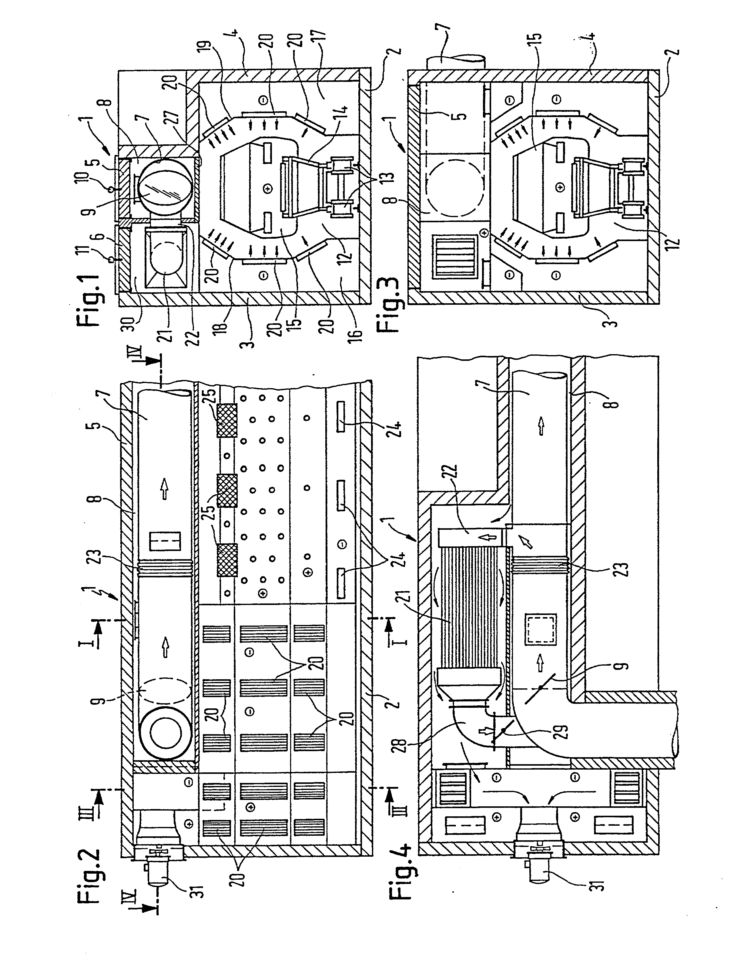
[0037] Referring now to FIG. 1 there is illustrated an example of the basic configuration of a paint dryer 1 in accordance with the invention. This cross-section as shown in FIG. 1 shows a paint dryer configured as an infeed and outfeed air lock 1 respectively. The air lock 1 comprises a floor 2 and sidewalls 3, 4. Connected to the floor are means 13 for guiding skids 14 so that vehicle bodies 15 secured thereto can be transported along a booth interior 12. The tunnel-type booth interior 12 is formed by the booth sidewalls 18, 19, the floor 2 as well as by a booth roof 27.

[0038] In the cross-sectional view as shown in FIG. 1 the infeed and outfeed air lock 1 respectively are equipped with inflow openings 20 through which the heated recirculation air flows into the booth interior 12.

[0039] In the roof zone of the paint dryer 1 a fresh air conduit duct 8 runs midway as viewed cross-sectionally, this duct being closed off at the top by a removable cover part 5. Provided on the removabl...


PUM


Abstract

The inventive paint dryer, comprises a cabin (12) for housing objects (15) that are to be painted and dried. At least one fresh air supply (8) is provided in order to introduce fresh air into an air circulation system pertaining to the dryer (1) resulting in the circulation of said air. At least one pure gas supply line (7) is provided, wherein thermally cleaned and heated waste air is introduced as a pure gas, thereby maintaining the waste gas circulated in the circulation system at the desired temperature in such a way that objects (15) arranged in the cabin (12) can be dried by radiation and/or convection. The pure gas supply line (7) is surrounded by the fresh air supply line (8) at least along a longitudinal pipe segment and at least in said longitudinal pipe section the pure gas supply pipe (7) is constructed in such a way as to allow for the transmission of heat to fresh air flowing into the fresh air supply (8). The invention also relates to a paint dryer unit comprising several paint dryer modules which are positioned one after the other and configured as paint dryers according to the invention.

Description

[0001] The invention relates to a paint dryer which is especially suitable for drying vehicle bodies, such as commercial vehicle or automobile bodies. One such paint dryer comprises a booth interior for accomodating painted items to be dried. At least one fresh air conduit is provided for introducing fresh air into a recirculation air system of the dryer. Recirculation air is circulated in the recirculation air system to maintain a desired process temperature in the dryer. In addition, at least one clean gas pipe is provided in which waste air subjected to thermal cleaning and thereby heated is supplied as clean gas with which the waste air circulated in the recirculation air system can be maintained at the desired temperature level so that the items located in the booth interior can be dried by radiation and / or convection.[0002] The invention relates furthermore to a paint drying system composed of a train of paint dryer modules. Each of the paint dryer modules has substantially th...

Claims


Application Information

Patent Timeline
IPC IPC(8): F26B3/04B05C9/14F26B3/30F26B9/00F26B15/12F26B23/02
CPCF26B3/305F26B15/12F26B2210/12F26B25/008F26B23/022
Inventor EISENACHER, FRIEDHELMSCHLAG, DIETERMULLER, HERBERT
Owner ABB FLAEKT AB
Why Eureka
Try Eureka