Vertebroplasty injection device and bone cement therefor

a technology of injection device and bone cement, which is applied in the direction of osteosynthesis device, prosthesis, instruments, etc., can solve the problems of relatively thin plunger rod, and affecting the effect of abrasion

Inactive Publication Date: 2002-10-24
DEPUY ACROMED INC
View PDF0 Cites 204 Cited by
  • Summary
  • Abstract
  • Description
  • Claims
  • Application Information

AI Technical Summary

Benefits of technology

[0016] The present inventors have found that providing a dual chamber, mixing-and-delivery device in which the delivery chamber houses an axially movable piston provides a number of advantages over the prior art Barker device.
[0017] First, the position of the axially movable piston can be manipulated during operation to pass over and occlude the entry port of the injection chamber during a stroke. The ability to occlude the entry port allows the user to selectively stop fluid communication between the injection chamber's exit opening and the reservoir, thereby isolating the bone cement (or other injectable material) present in the injection chamber. The isolated bone cement may then be advantageously injected into the patient in small discrete quantities (such as 0.5-1 cc per stroke). This capability provides the surgeon with highly specific control of the quantity of injected cement, a quality not found in other high pressure vertebroplasty injection devices.
[0018] Second, the axially movable piston can be made to sealingly fit within a small (e.g., 1 cc) tubular injection chamber so as to force the discrete quantity of bone cement in the injection chamber in a predetermined direction under high pressure. Accordingly, a mixing-and-delivery device having both high-pressure delivery capability and a compact size is now possible.
[0019] Lastly, the axially movable piston may be attached to a lever to increase the mechanical advantage of the force used to axially move the piston, thereby further increasing the pressure within the injection chamber.
[0020] For these reasons, the device of the present invention can deliver discrete quantities of bone cement at pressures suitable for vertebroplasty (preferably, at least 1000 psi (.about.6.89 MPa), more preferably, at least 2000 psi (.about.13.8 MPa)) while maintaining overall device dimensions which are desirable for vertebroplastic surgeries. Accordingly, the device of the present invention provides significant technical advances over the conventional mixing / injection devices used in the bone cement procedures.
[0055] c) means for preventing back flow from the exit opening of the injection chamber.

Problems solved by technology

Although this procedure has found success, it has also met with some problems.
For example, Jensen reports that the open-air mixing of the precursor materials produces problematic fumes.
Also, when the plastic plunger in a 1 mm syringe is pressed against the viscous cement in the syringe barrel, the appreciable resistance of the cement to this pressure may cause the relatively thin plunger rod to collapse.
Although this precaution enhances the feasibility of the procedure, it requires loading twice as many syringes, thereby increasing the total time of the procedure.
In addition, the pressures which can be generated by manual operation of 1 ml syringes are fairly low.
However, Nilson discloses a conventional delivery system having a conventional plunger in a single chamber for delivering the bone cement, and so does not provide high pressure delivery.
As fluid is delivered via pressure developed by a conventional plunger, this device suffers from the same low pressure deliveries experienced by syringes using conventional plungers.
These features make this device very complicated to operate.
Lastly, Reyman does not disclose an injection chamber having a sterile inner surface.
However, these devices often provide inadequate control of the delivery of the bone cement, and may pose safety concerns in applications such as vertebroplasty wherein control of the injected material is of paramount importance.
Haubrich does not disclose an impermeable piston in the injection chamber.

Method used


Image

  • Vertebroplasty injection device and bone cement therefor
  • Vertebroplasty injection device and bone cement therefor
  • Vertebroplasty injection device and bone cement therefor

Examples


first embodiment

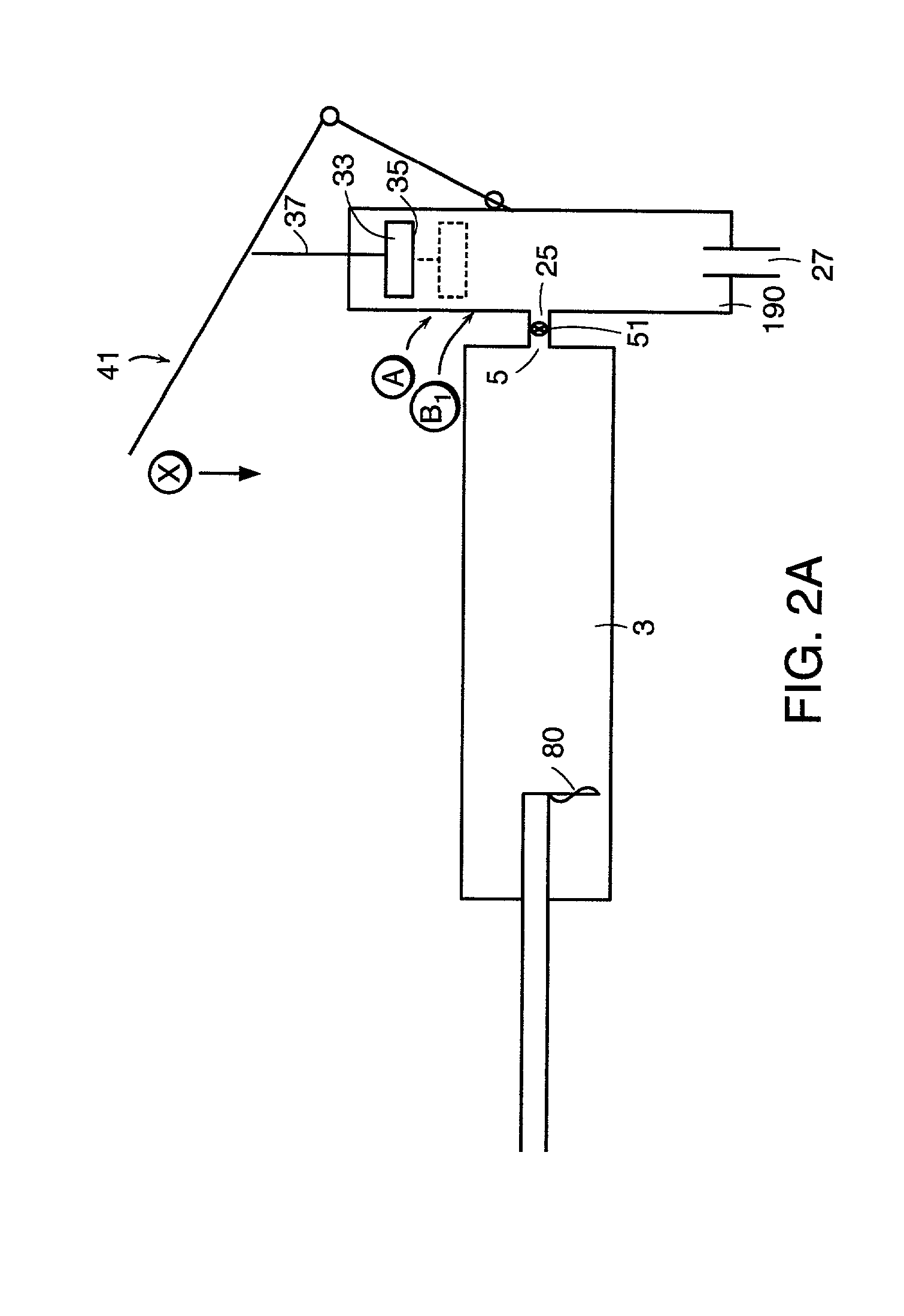
[0151] In accordance with the first embodiment, it is preferred that the the first and second end portions of the injection chamber define a first axis within the inner surface, wherein the first piston comprises a sidewall having a shape corresponding to the inner surface of the injection chamber, and the first piston is received within the inner surface to allow axial movement of the first piston along the first axis within the inner surface. The piston correspondence with inner surface shape allows easy axial movement of the piston.

[0152] It is preferred that the first piston is slidably received within the inner surface to allow sliding movement of the first piston along the first axis within the inner surface.

[0153] It is preferred that the shape of the first piston sidewall provides substantial sealing engagement with the inner surface. This conditions prevents the flow of bone cement therebetween.

[0154] It is preferred that the first piston has an inner face facing the exit o...

ninth embodiment

[0209] In accordance with the ninth embodiment, it is preferred that the first end portion of the lever is pivotally attached to the device.

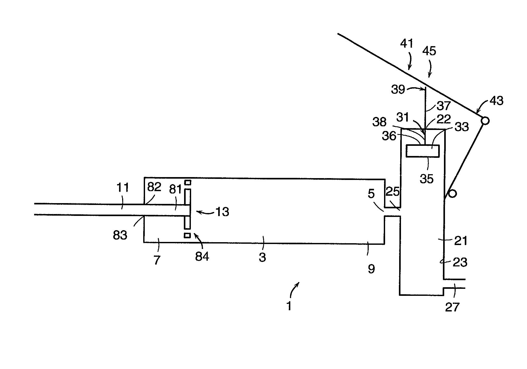
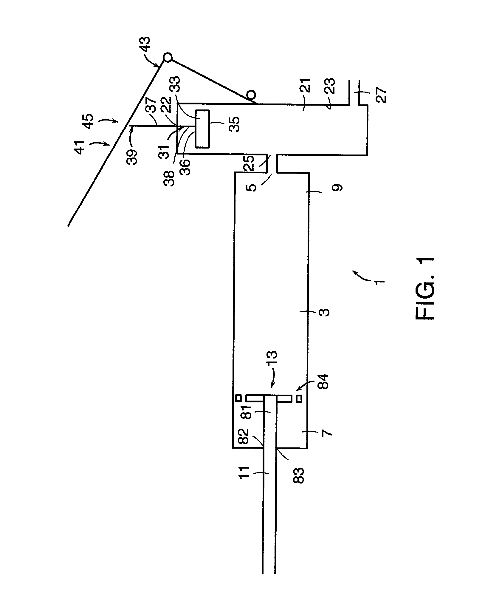
[0210] In accordance with the tenth embodiment (which requires a means for creating a vacuum in the injection chamber), it is preferred that the device further comprises means for maintaining pressure within the reservoir. Preferably, the means for creating a vacuum comprises a first piston disposed within the inner surface of the injection chamber.

[0211] In accordance with the eleventh embodiment (which requires an O-ring), it is preferred that the device further comprises a first piston having a sidewall disposed within the inner surfaces of the injection chamber, wherein the O-ring is disposed between the sidewall and the inner surface of the injection chamber.

[0212] In many orthopaedic surgeries, a radiopaque compound such as barium or barium sulfate (BaSO.sub.4) is conventionally added to the bone cement mixture so that the cement can be se...


PUM

PropertyMeasurementUnit
angleaaaaaaaaaa
surface volumeaaaaaaaaaa

Abstract

This invention relates to a mixing and delivery device suitable for delivering injectable biomaterials, and to preferred bone cement formulations.

Description

[0001] In vertebroplasty, the surgeon seeks to treat a compression fracture of a vertebra by injecting bone cement such as PMMA into the fracture. In one clinical report, Jensen et al., AJNR: 18 November 1997, Jensen describes mixing two PMMA precursor components (one powder and one liquid) in a dish to produce a viscous bone cement; filling 10 ml syringes with this cement, injecting it into smaller 1 ml syringes, and finally delivering the mixture into the desired area of the vertebral body through needles attached to the smaller syringes.[0002] Although this procedure has found success, it has also met with some problems. For example, Jensen reports that the open-air mixing of the precursor materials produces problematic fumes. Also, when the plastic plunger in a 1 mm syringe is pressed against the viscous cement in the syringe barrel, the appreciable resistance of the cement to this pressure may cause the relatively thin plunger rod to collapse. To minimize this danger, only abou...

Claims


Application Information

Patent Timeline
Patent Type & Authority Applications(United States)
IPC IPC(8): A61B17/88A61F2/44A61F2/46A61K9/14A61K49/04A61L24/00A61L24/02A61B17/56B01F11/00B01F13/00B01F15/02
CPCA61B17/8822A61F2/44A61L24/0089A61L24/02B01F2215/0029B01F13/002B01F13/0023B01F15/0279B01F11/0082B01F31/441B01F33/50112B01F33/251B01F33/5011B01F35/754251B01F2101/20
Inventor VOELLMICKE, JOHN C.MRAZ, PAUL J.SOMMERICH, ROBERTBUONANNO, JOHNHARRIS, NOLENEWATKINS, NEILKOWALSKI, RICKPETERSON, FRANCISBJORK, TODDDUFFY, MARK
Owner DEPUY ACROMED INC
Why Eureka
Try Eureka