Infrared projector

a projector and infrared technology, applied in the direction of material analysis using wave/particle radiation, instruments, nuclear engineering, etc., can solve the problems of serious errors, limited heat dissipation, and worsening of the temporal response in the temperature change from a high temperature to a low temperature, so as to achieve high spatial resolution, high temporal resolution, and control wavelength and luminance characteristics

Inactive Publication Date: 2002-10-31
MITSUBISHI ELECTRIC CORP
View PDF0 Cites 6 Cited by
  • Summary
  • Abstract
  • Description
  • Claims
  • Application Information

AI Technical Summary

Benefits of technology

0016] The present invention was made in order to solve the problems described above, and it is an object of the present invention to provide an infrared projector in which it is not necessary to develop arrayed elements radiating infrared radiation, a high temporal resolution and a high spatial resolution are obtained, the simulation of a high temperature body is obtained, the wavelength and luminance characteristics are controlled, a high contrast and a high simulation accuracy are made available, and so on.

Problems solved by technology

When the amount of the heat dissipation is increased, as the fine heating element does not rise in temperature, the amount of heat dissipation is limited.
This is because the temporal response in temperature change from a high temperature to a low temperature is worsened in this projector.
The maximum temperature at which projection can be made using the projector is 762K, and projection at temperatures higher than this cannot be made otherwise serious errors will occur.
In this way, when the amount of infrared radiation is low, the infrared projector has lower contrast and becomes difficult to use.
a) it was required to newly develop a fine heating element array for specialized use in an infrared projector, and the heating element array was expensive,
b) because the temporal response to temperature changes is poor since heating elements are used, and because a spacing is required between elements in the array as the heating elements need lead wires, and further because of some other reasons, the temporal resolution and spatial resolution were poor,
c) because the temperature of the fine heating element is limited, the simulation of a high-temperature body could not be performed,
d) the intensity distribution of infrared radiation generated by the fine heating element array had poor contrast, the accuracy of the simulation was poor, and some other problems existed.

Method used


Image

  • Infrared projector
  • Infrared projector
  • Infrared projector

Examples


embodiment 1

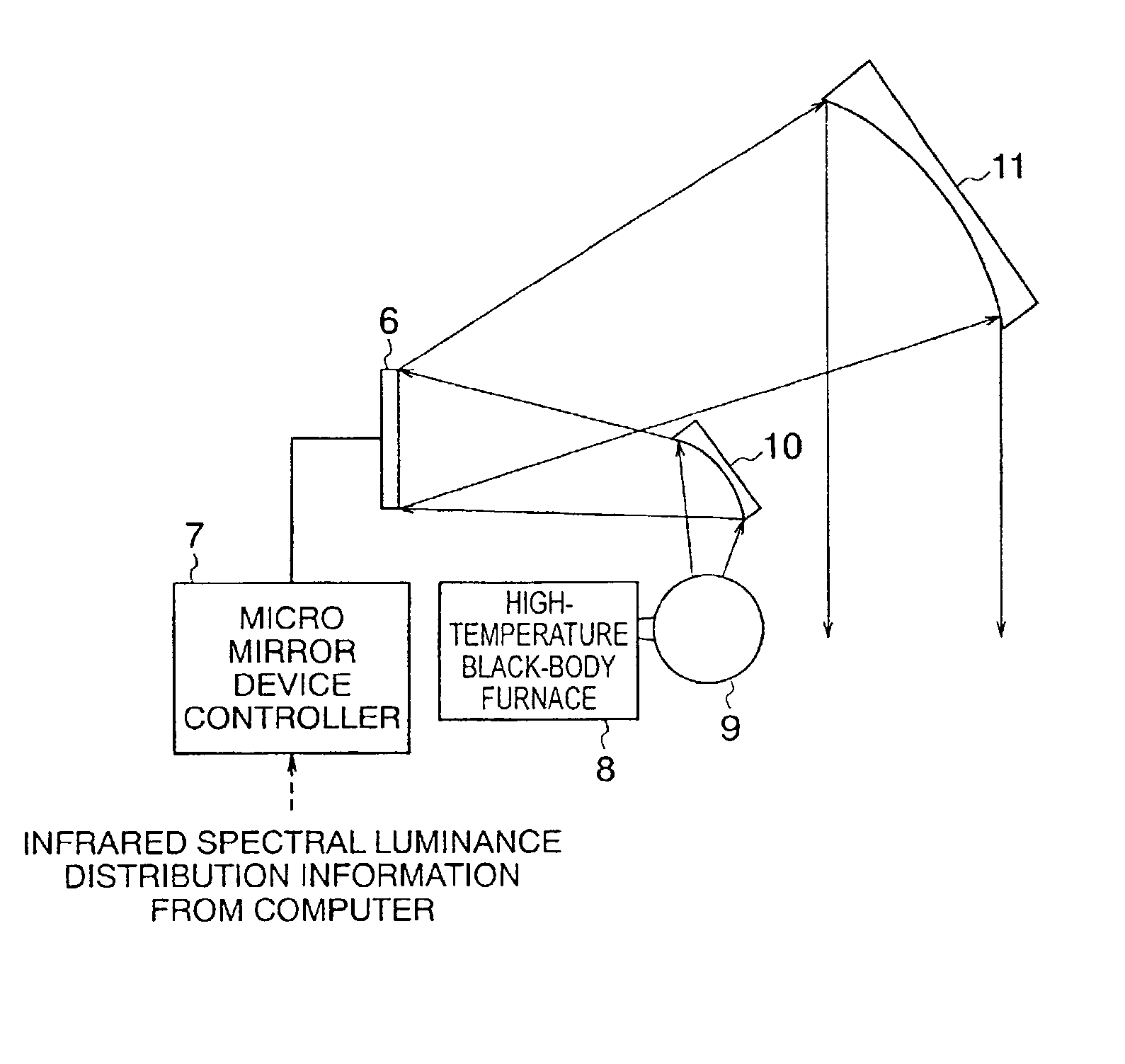
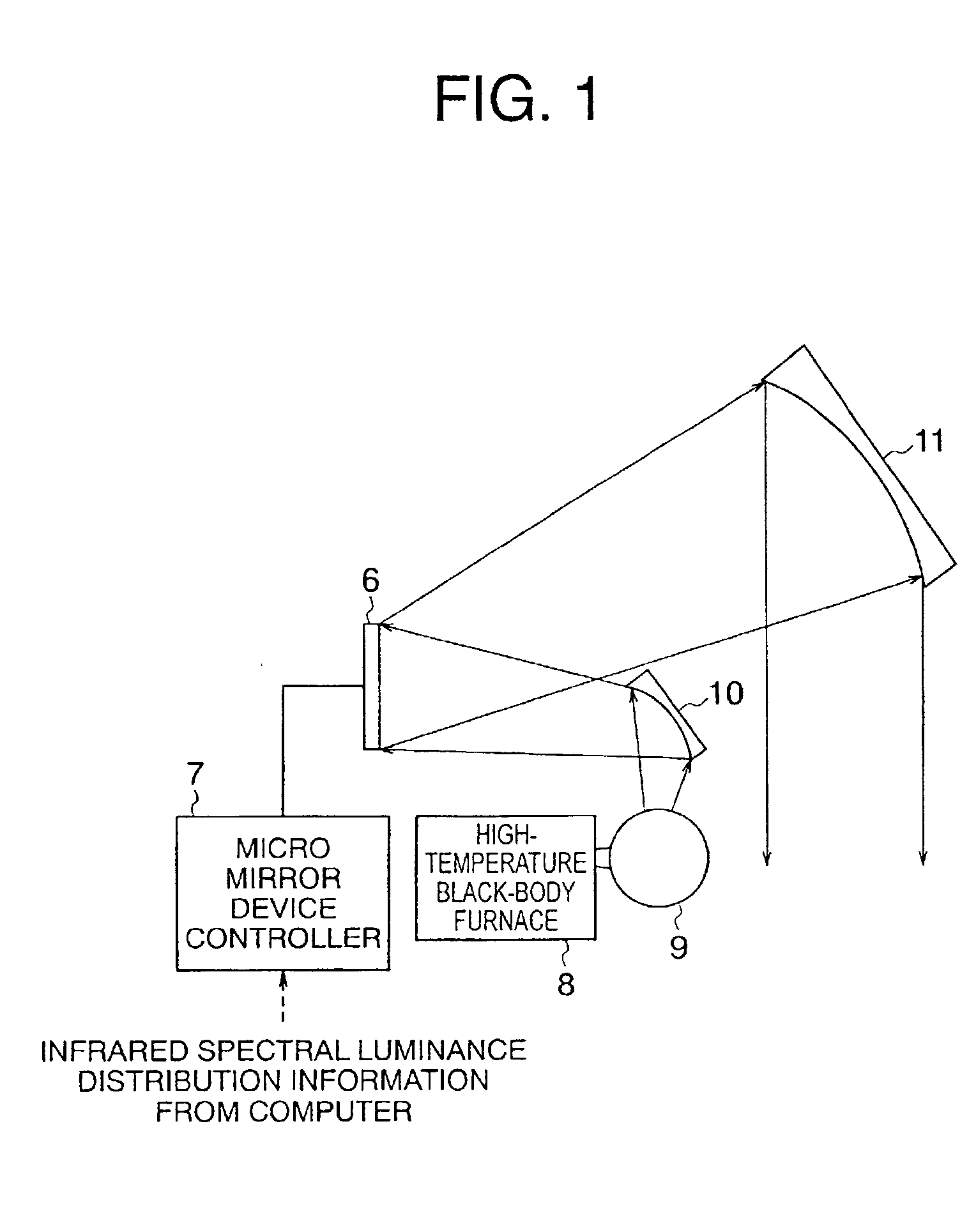
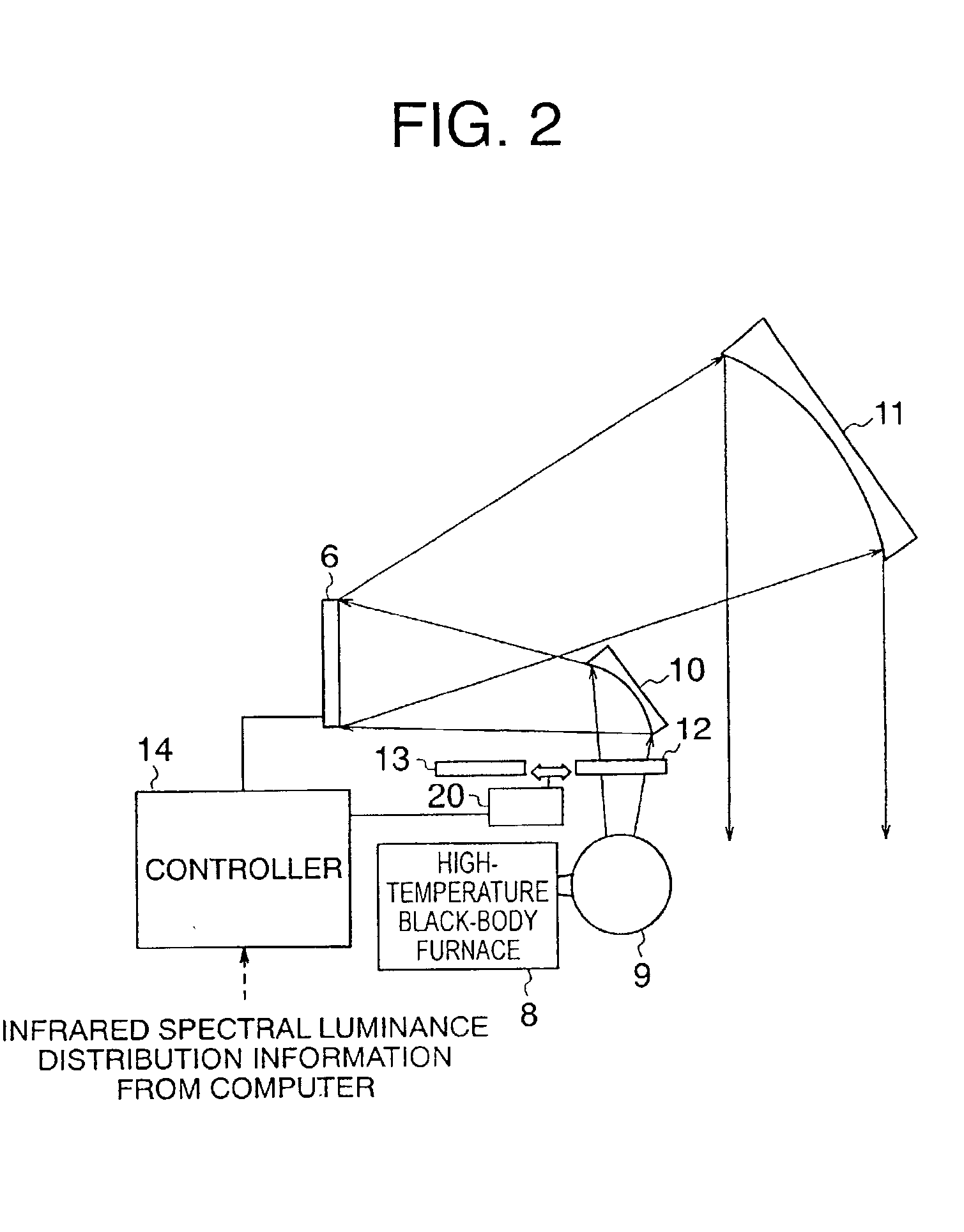
[0041] A bandpass filter 12, a bandpass filter 13 having a passband different from that of the bandpass filter 12, a controller 14 for the bandpass filters 12 and 13 and the micromirror device 6, and a movable supporting means 20 for switching the bandpass filters 12 and 13 and fixing and supporting either of them at a desired location under the control of the controller 14 are shown, and the other components are the same as in Moreover, the bandpass filters 12 and 13 and the movable supporting means 20 constitute an infrared wavelength selection means.

[0042] Next, the operation is described. The controller 14 receives the infrared spectral luminance distribution information from a computer and controls the wavelength characteristic by controlling the bandpass filters 12 and 13 and the micromirror device 6.

[0043] Hereinafter, one micromirror in a two-dimensional arrangement is selected and its operation is described. Based on the infrared luminance information in the passband of th...

embodiment 2

[0044] Moreover, in EMBODIMENT 2, two kinds of bandpass filters were used, and it is apparent that the more the wavelengths are divided, the more the accuracy of the wavelength characteristics is improved. Accordingly, three or more kinds of bandpass filters may be used.

embodiment 3

[0045] In EMBODIMENT 2 described above, the bandpass filters were used as optical elements for limiting the passband, but next, an example using diffraction gratings is shown as an optical element for limiting the passband. FIG. 3 shows the construction of an infrared projector according to another example of the present invention in such a case.

[0046] A diffraction grating 15, a diffraction grating 16 having a different grating pitch from that of the diffraction grating 15, a controller 17 for the diffraction gratings 15 and 16 and the micromirror device 6, a movable supporting means 21 for switching the diffraction gratings 15 and 16 and fixing and supporting either of them at a desired location with a desired tilting in accordance with control of the controller 17 are shown, and the other components are the same as in EMBODIMENT 1. Moreover, the diffraction gratings 15 and 16 and the movable supporting means 21 constitute an infrared wavelength selection means.

[0047] Next, the op...


PUM

PropertyMeasurementUnit
temperatureaaaaaaaaaa
temperaturesaaaaaaaaaa
infrared emissivityaaaaaaaaaa

Abstract

To provide an infrared projector in which it is not necessary to develop arrayed elements radiating infrared radiation, a high temporal resolution and a high spatial resolution are made available, the simulation of a high-temperature body is made possible, the wavelength and luminance characteristics are controlled, a high contrast and a high simulation accuracy are made available, and so on. A micromirror device (6) as an optical modulator for changing the direction of reflection by providing a plurality of mirrors and changing the direction of each of the plurality of mirrors independently, a controller (7) for controlling the direction of each mirror of the micromirror device, and infrared light sources (8, 9, and 10) for irradiating the micromirror device with infrared light are provided.

Description

[0001] This invention relates to an infrared projector for projecting infrared radiation analogous to two-dimensional infrared spectral luminance distribution information about an infrared scene, etc., produced by a computer, etc, based on the luminance distribution information. For example, the infrared projector is used in the evaluation of infrared equipment in such a way that an infrared image can be obtained by imaging infrared radiation projected by the projector using an infrared imaging device, that the infrared spectral luminance data and the infrared image are compared, and that the imaging capability of the infrared imaging device is evaluated by the degree of degradation of the infrared image.[0002] FIG. 5 is a conventional infrared projector shown in George C. Goldsmith, "Characterization measurement of the wideband infrared scene projector resistor array", SPIE, Vol. 2742, P25-37(1996). A fine heating element array 1, a controller 2 for the fine heating element array 1...

Claims


Application Information

Patent Timeline
Patent Type & Authority Applications(United States)
IPC IPC(8): G02B5/08G02B5/04G02B5/18G02B17/00G02B26/08G03B21/14
CPCG02B26/0841
Inventor SUZUKI
Owner MITSUBISHI ELECTRIC CORP
Why Eureka
Try Eureka