Optical pickup apparatus and focusing control method

Inactive Publication Date: 2002-10-31
PIONEER CORP
View PDF5 Cites 35 Cited by
  • Summary
  • Abstract
  • Description
  • Claims
  • Application Information

AI Technical Summary

Problems solved by technology

However, as can be seen from FIG. 2B showing the focus error signal FE when the capture range is 1/4 of the layer interval, the focus error signals from the recording layers affect each other, and the resulting composite focus error signal FE (solid line) has an error, and therefore a light spot cannot be focused on a desired recording layer.
However, a reduction in the capture range makes the focus pull-in difficult, and a disturbance such as vibration during recording/rep

Method used


Image

  • Optical pickup apparatus and focusing control method
  • Optical pickup apparatus and focusing control method
  • Optical pickup apparatus and focusing control method

Examples


first embodiment

[0054] First Embodiment

[0055] A recording and / or reproducing apparatus (hereinafter, ref erred to as recording / reproducing apparatus) including an optical pickup according to preferred embodiments of the present invention will be described.

[0056] Optical Pickup

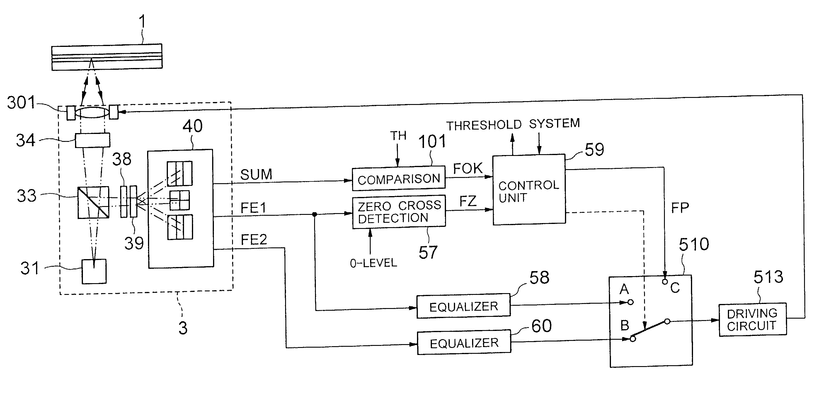
[0057] FIG. 3 is a view showing the configuration of an optical pickup 3 according to a first embodiment of the present invention.

[0058] The optical pickup 3 includes a semiconductor laser 31 as a light source, a grating 32, a polarization beam splitter 33, a collimator lens 34, a mirror 35, a 1 / 4 (quarter)-wavelength plate 36, an objective lens 37, an astigmatism generating optical element 38 of a light transmitting material such as a cylindrical lens, a diffraction optical element 39 such as a holographic lens, and a photodetector 40 including a 0-th order diffracted light photodetector 400 and .+-.1st order diffracted light photodetectors 401, 402. The optical disc 1 is placed apart from the objective lens 37 on the turntab...

second embodiment

[0112] Second Embodiment

[0113] A recording / reproducing apparatus including an optical pickup according to a second embodiment of the present invention will be described.

[0114] Irradiation Optical System in Optical Pickup

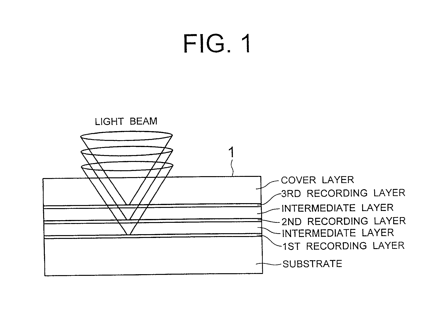
[0115] FIG. 14 is a view showing the configuration of an optical pickup 1003 according to a second embodiment of the present invention. A multi-layer disc such as an optical disc 1001 having three recording layers as shown in FIG. 1 is placed on the turntable and apart from an objective lens 1037 in the optical pickup 1003. The turntable is rotated by a spindle motor (not shown)

[0116] The optical pickup 1003 includes an irradiation optical system including a semiconductor laser 1031 as a light source, a collimator lens 1032, a polarization beam splitter 1033, a mirror 1035, a 1 / 4 wavelength plate 1036, and the objective lens 1037.

[0117] The optical pickup 1003 includes a focus actuator 1301 supporting the objective lens 1037. The focus actuator 1301 performs focus se...


PUM


Abstract

An optical pickup apparatus having an irradiation optical system for condensing a light beam on a track of a recording plane and a photodetection optical system for guiding return light to a photodetector to detect a focal error includes a holographic lens provided in the optical path of the return light for outputting 0-th and ±1st order diffracted lights based on the return light; an optical element provided in front of or behind the holographic lens for providing astigmatism; photodetectors for receiving the 0-th and ±1st order diffracted lights; and servo-signal generating operation circuits connected to the photodetectors for generating a first and second focus error signals having a first and second capture ranges based on the output signal of the photodetector.

Description

[0001] 1. Field of the Invention[0002] The present invention relates to an optical pickup of a recording / reproducing apparatus for an optical recording medium such as an optical disc, and more particularly, to an optical pickup capable of controlling the optimum focusing position of a light beam focused on a recording plane of a recording medium such as an optical disc having multiple recording layers, and a focusing control method therefor.[0003] 2. Description of the Related Art[0004] There has been developed a high recording density and mass storage information recording medium referred to as a DVD (Digital Versatile Disc) and a system using the medium. A DVD having a single recording layer on one side of the disc has a capacity of 4.7 GB. There has been developed a two-layer DVD which is compliant with the DVD standard to increase the recording capacity. The use of a high NA optical system and a shorter wavelength light-source has been studied for the next generation multi-layer...

Claims


Application Information

Patent Timeline
IPC IPC(8): G11B7/00G11B7/085G11B7/09G11B7/13
CPCG11B7/08511G11B7/0909G11B7/0912G11B7/094G11B2007/0013G11B7/0946G11B7/131G11B7/133G11B7/0943
Inventor OGASAWARA, MASAKAZUKIKUCHI, IKUYA
Owner PIONEER CORP
Why Eureka
Try Eureka