Bistable molecular mechanical devices with a band gap change activated by an electric field for electronic switching, gating, and memory applications

a molecular mechanical device and band gap change technology, applied in the field of molecular systems, can solve the problems of slow switching time of molecules, irreversible switches, and large energy expenditure to toggle switches, and achieve the effect of fast switching time, easy and cheap making, and high efficiency

Inactive Publication Date: 2002-11-28
HEWLETT PACKARD DEV CO LP
View PDF14 Cites 48 Cited by
  • Summary
  • Abstract
  • Description
  • Claims
  • Application Information

AI Technical Summary

Benefits of technology

0017] Thus, the molecule is never oxidized nor reduced in the toggling of the switch. Also, the part of the molecule that moves is quite small, so the switching

Problems solved by technology

The primary problem with the rotaxane was that it is an irreversible switch.
This requires the expenditure of a significant amount of energy to toggle the switch.
In addition, the large and complex

Method used


Image

  • Bistable molecular mechanical devices with a band gap change activated by an electric field for electronic switching, gating, and memory applications
  • Bistable molecular mechanical devices with a band gap change activated by an electric field for electronic switching, gating, and memory applications
  • Bistable molecular mechanical devices with a band gap change activated by an electric field for electronic switching, gating, and memory applications

Examples


example 1

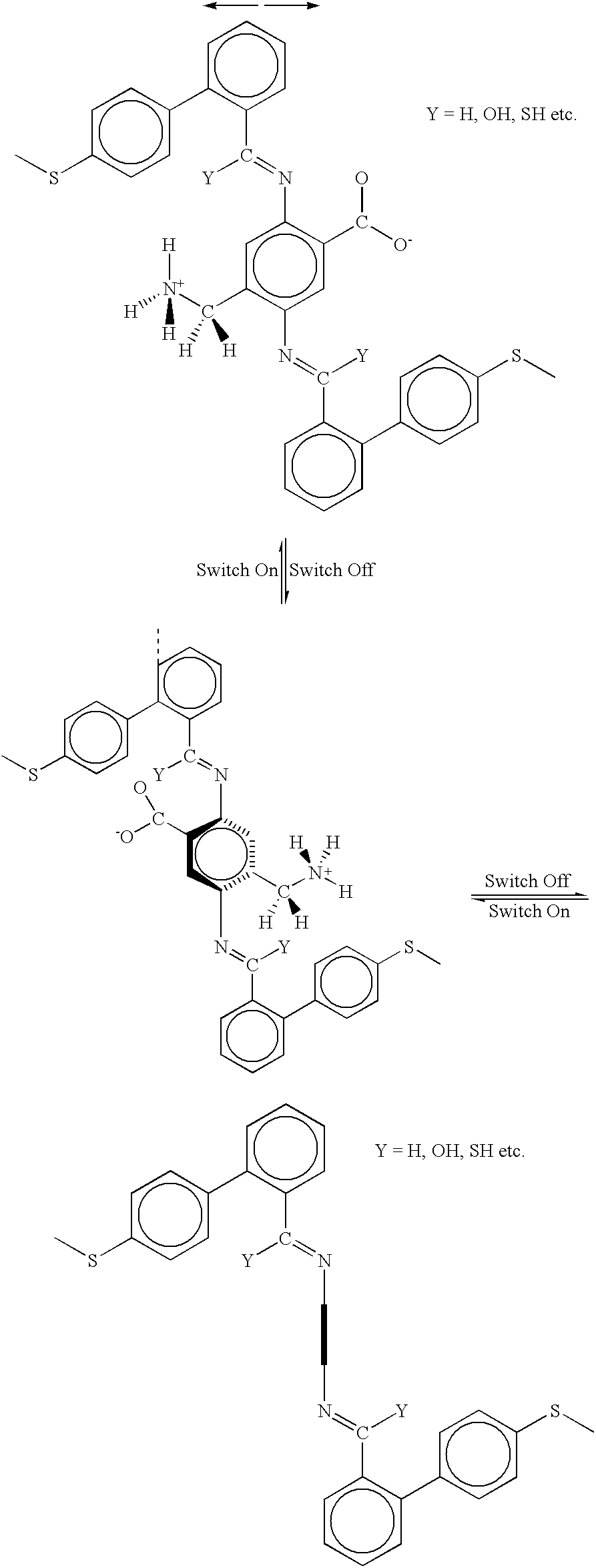
[0095] The molecule shown above (Example 1) has been designed with the internal rotor 32 perpendicular to the orientation or current-flow axis of the entire molecule 30. In this case, the external field is applied along the orientation axis of the molecule 30 as pictured--the electrodes (vertical dotted lines) are oriented perpendicular to the plane of the paper and perpendicular to the orientation axis of the molecule 30. Application of an electric field oriented from left to right in the diagrams, as indicted by the double-headed arrow, will cause the rotor 32 as pictured in the upper diagram to rotate to the position shown on the lower right diagram, and vice versa. In this case, the rotor 32 as pictured in the lower right diagram is not coplanar with the rest of the molecule, so this is the OFF or low conductivity state of the molecule, whereas the rotor is co-planar with the rest of the molecule on the upper diagram, so this is the ON or high conductivity state of the molecule....

example 2

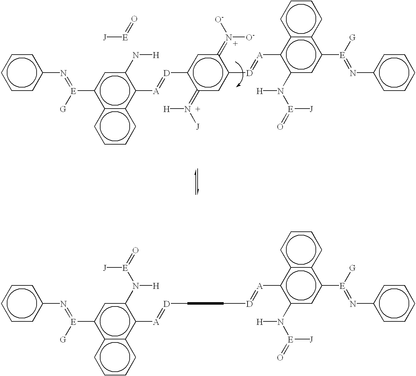
[0098] The molecule shown above (Example 2) has been designed with the internal rotor parallel to the orientation axis of the entire molecule. In this case, the external field is applied perpendicular to the molecular axis--the electrodes are oriented parallel to the long axis of the molecule and can be either perpendicular or parallel to the plane of the above model structures. For example, application of an electric field to the upper molecule shown above where the field lines are perpendicular to the molecular axis and pointing upward will cause the rotor as pictured in that diagram to rotate to approximately 90 degrees and appear edge on, as shown in the lower molecular diagram above, and vice versa. In this case, the rotor as pictured in the lower diagram is not coplanar with the rest of the molecule, so this is the OFF or low conductivity state of the molecule, whereas the rotor is coplanar with the rest of the molecule on the upper diagram, so this is the ON or high conductiv...

example 3

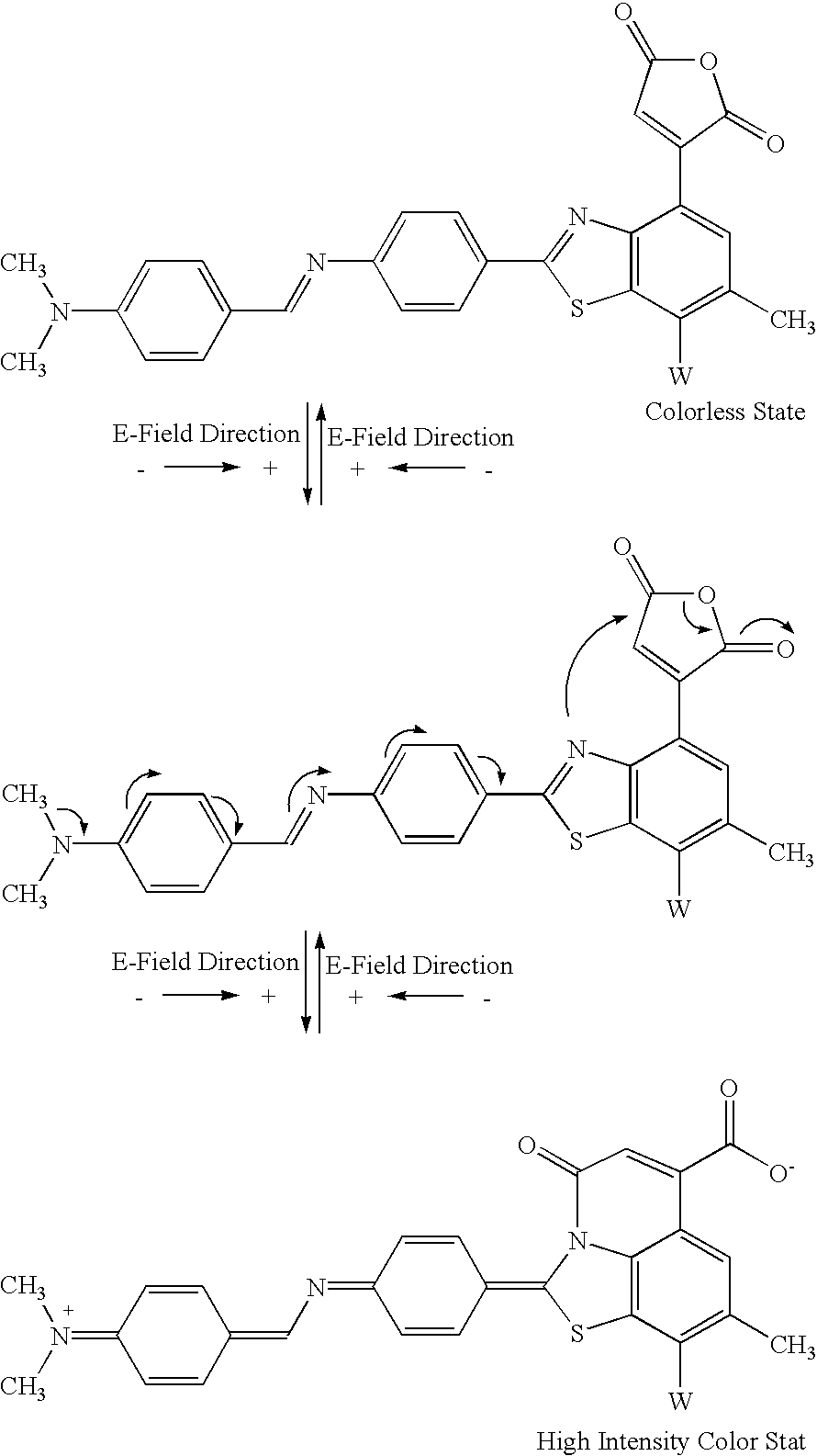
[0114] The letter W in Example 3 is used to designate an electron-withdrawing group, e.g., nitro, carboxylic acid derivatives, ketone, aldehyde, sulfone, sulfoxide, sulfuric acid or its derivatives, sulfenic acid or its derivatives, halogen or halogenated hydrocarbon, nitrile or nitrile derivatives, or hydrocarbon (saturated or unsaturated) with at least one of the above-mentioned electron-withdrawing groups.

[0115] An example of an E-field induced band gap change involving the formation of a molecule-metal complex or a molecule-Lewis acid complex is shown below (Example 4): 4


PUM


Abstract

Molecular systems are provided for electric field activated switches, such as a crossed-wire device or a pair of electrodes to which the molecular system is linked by linking moieties. The crossed-wire device comprises a pair of crossed wires that form a junction where one wire crosses another at an angle other than zero degrees and at least one connector species connecting the pair of crossed wires in the junction. The connector species comprises the molecular system, which has an electric field induced band gap change, and thus a change in its electrical conductivity, that occurs via one of the following mechanisms: (1) molecular conformation change; (2) change of extended conjugation via chemical bonding change to change the band gap; or (3) molecular folding or stretching. Nanometer-scale reversible electronic switches are thus provided that can be assembled easily to make cross-bar circuits, which provide memory, logic, and communication functions.

Description

[0001] The present application is a continuation-in-part application of Ser. No. ______, filed ______ [PD-10003866-1], which in turn is a continuation-in-part application of Ser. No. ______, filed Dec. 14, 2000 [PD-10004762-1].[0002] The present application is also related to the following applications and patents: Ser. Nos. 09 / 280,048 ("Chemically Synthesized and Assembled Electronic Devices"); 09 / 280,225 ("Molecular Wire Crossbar Interconnects for Signal Routing and Communications"); 09 / 282,045 ("Molecular Wire Crossbar Logic"); 09 / 282,049 ("Demultiplexer for a Molecular Wire Crossbar Network"); and 09 / 280,188 ("Molecular Wire Transistors"), all filed on Mar. 29, 1999, and U.S. Pat. No. 6,128,214, issued on Oct. 3, 2000 ("Molecular Wire Crossbar Memory").[0003] The present application is an improvement over the foregoing applications and patent in that it is directed to classes of molecules that provide switching from one state to a different state, characterized by a change in th...

Claims


Application Information

Patent Timeline
IPC IPC(8): G02F1/15H01L27/10G02F1/17G11C13/02H01L49/02H01L51/05H01L51/30H03K17/00
CPCB82Y10/00G02F1/15G02F1/174G11C2213/81G11C13/04G11C2213/14G11C2213/77G11C13/02H10K10/50G11C13/00G11C11/00H10K10/00
Inventor ZHANG, XIAO-ANWILLIAMS, R. STANLEYVINCENT, KENT D.
Owner HEWLETT PACKARD DEV CO LP
Why Eureka
Try Eureka