Cutting tool

Inactive Publication Date: 2002-12-05
DISCO CORP
View PDF24 Cites 15 Cited by
  • Summary
  • Abstract
  • Description
  • Claims
  • Application Information

AI Technical Summary

Problems solved by technology

According to the prevent inventors' experience, conventional cutting tools pose the problem that the cutting tips do not wear badly and are still usable, but cracks extendin

Method used


Image

  • Cutting tool
  • Cutting tool
  • Cutting tool

Examples


example 6 to 10

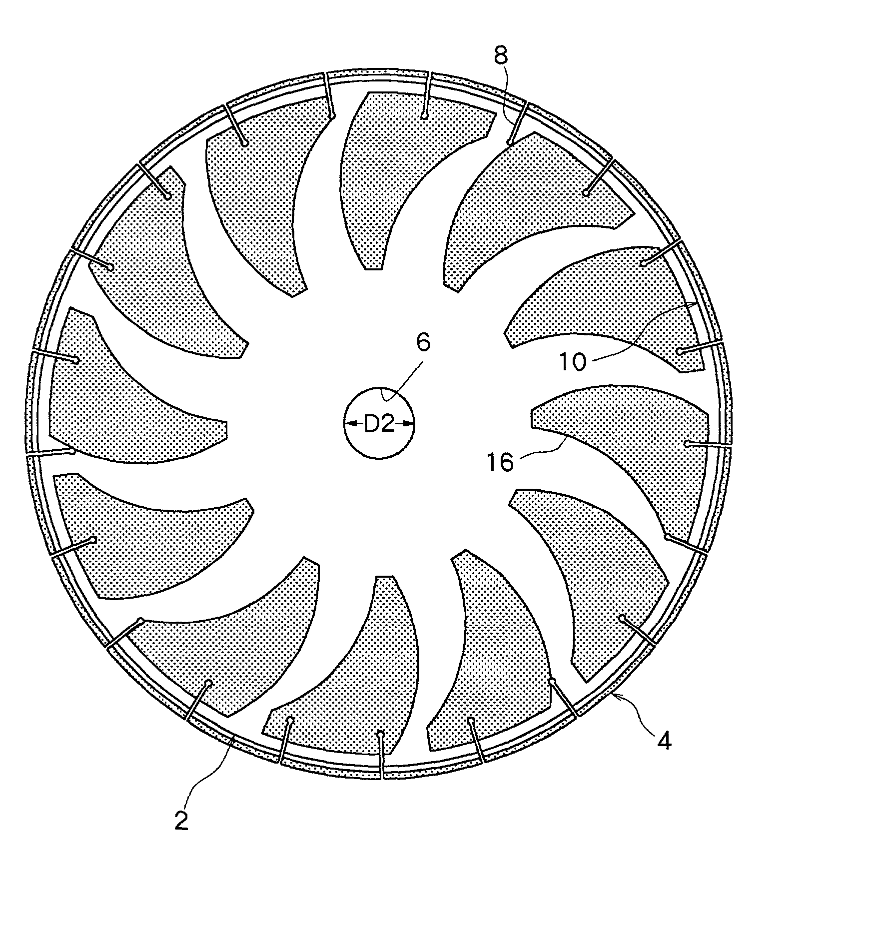
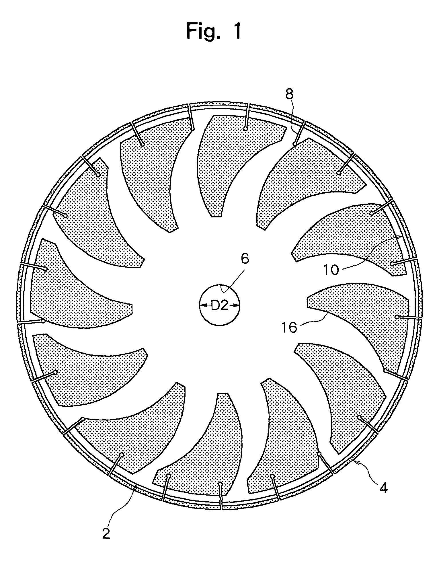
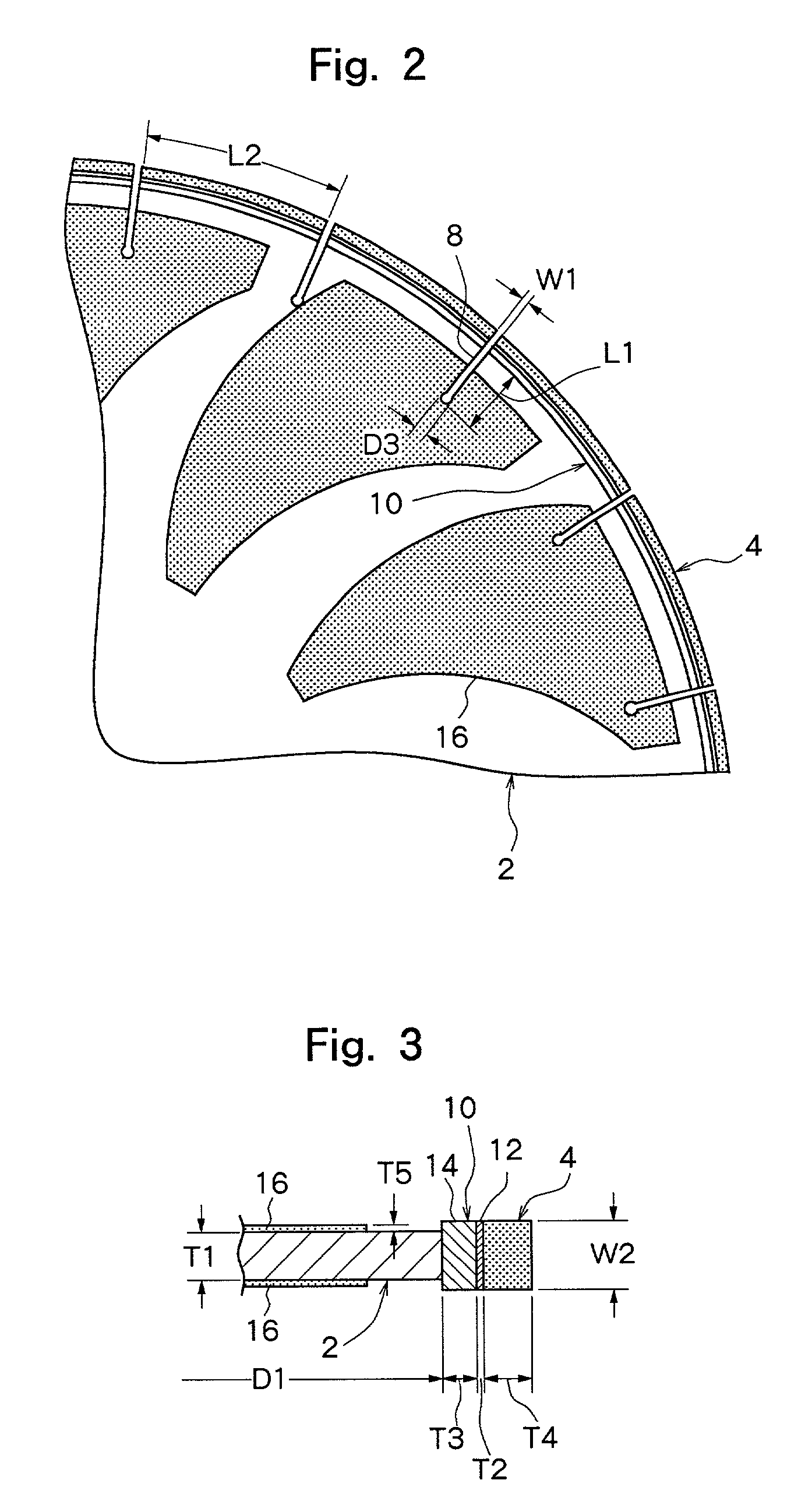
[0021] Five cutting tools were produced in the same manner as in Examples 1 to 5, except that an abrasive grain electrodeposited layer in a configuration as shown in FIGS. 1 to 3 was disposed on each of the side surfaces of the base plate. The abrasive grain electrodeposited layer was formed by electrodepositing silicon carbide particles with a particle size of 100 to 120 .mu.m with the use of nickel as a metal for electroplating. The thickness T5 of the abrasive grain electrodeposited layer was 200 .mu.m, and the volume ratio of the abrasive grains was 37.5 (concentration: 150). The same cutting test as in Examples 1 to 5 was conducted. The results are shown in Table 1.

1 TABLE 1 Life Cutting speed (seconds) (no. of cuttings) Maximum Minimum Average Ex. 1 1463 28 50 46 Ex. 2 1497 30 48 44 Ex. 3 1471 31 51 48 Ex. 4 1452 32 48 43 Ex. 5 1517 34 46 45 Comp. Ex. 1 600 38 60 50 Comp. Ex. 2 862 40 64 53 Comp. Ex. 3 953 37 63 56 Comp. Ex. 4 701 42 62 51 Comp. Ex. 5 539 43 65 55 Ex. 6 1521 2...


PUM

PropertyMeasurementUnit
Abrasiveaaaaaaaaaa

Abstract

A cutting tool is composed of a circular base plate, and a plurality of arc-shaped cutting tips fixed to the outer peripheral surface of the base plate and spaced from each other in a circumferential direction. The base plate is formed from stainless steel.

Description

[0001] This invention relates to a cutting tool used to cut a hard-to-cut material such as a cast iron tube.DESCRIPTION OF THE PRIOR ART[0002] A cutting tool to be rotated at a high speed is used for cutting a hard-to-cut material such as a cast iron tube. A typical example of such a cutting tool is a cutting tool called a segmental circular saw. Such a cutting tool is composed of a circular base plate, and a plurality of cutting tips fixed to the outer peripheral surface of the base plate and spaced from each other in the circumferential direction. Normally, a plurality of slits extending radially inwardly from the outer peripheral surface of the base plate are formed in the base plate, and the cutting tips are arranged between the slits.[0003] According to the prevent inventors' experience, conventional cutting tools pose the problem that the cutting tips do not wear badly and are still usable, but cracks extending from the slits occur in the base plate in relatively short periods...

Claims


Application Information

Patent Timeline
IPC IPC(8): B23D61/02B23D61/04B23D61/18B24D5/12B24D18/00
CPCB23D61/028B23D61/04B24D18/0018B24D5/123B23D61/18Y10T83/9319Y10T83/9377
Inventor OKUDA, YUKIOMATSUMOTO, HIROKAZU
Owner DISCO CORP
Why Eureka
Try Eureka