Electronic device remote control method and electronic device management facility

a technology of electronic devices and remote control, applied in the direction of testing/monitoring control systems, instruments, data switching networks, etc., can solve the problems of user inability to perform remote connection communication, user's portable phone becomes less portable, and the cost of running is consequently high, so as to achieve a high level of process capability

Inactive Publication Date: 2002-12-05
VIVINT INC
View PDF9 Cites 388 Cited by
  • Summary
  • Abstract
  • Description
  • Claims
  • Application Information

AI Technical Summary

Benefits of technology

[0019] The present invention has been made with a view to providing an improved method for the remote control of home-located electronic devices and a management facility. The present invention utilizes a simple server to control home-located electronic devices which does not require a high level of process capability; and a simple terminal (e.g. a portable telephone), for performing the remote control of the home-located electronic devices.
[0021] In the method for the remote control of home-located electronic devices of the present invention, the management facility obtains the status of the home-located electronic devices from the server when it receives a request from the terminal, and receives the details for controlling the home-located electronic devices from the terminal based on the obtained status information, and transmits the details to the server. Thus, remote control of home-located electronic devices can be performed by utilizing a simple server, which has the advantage that large processing power is not required. Further, a simple terminal a portable telephone can be used.

Problems solved by technology

While such devices are frequently used independently, due to the lack of a common user interface, they are rarely used in conjunction with each other.
In remote control method (a), the home server has to be connected to the Internet all of the time and the cost of running is consequently high.
However, there are other restrictions when using remote control method (b) in that a portable terminal such as a portable telephone has a function, at best, of being able to connect to the Internet and it is not compatible with a remote connection function installed in the home server, such as a RAS.
Therefore, the user is not able to perform communication with regard to the remote connection function.
Also, when a remote control function is installed in a portable phone, there is a problem that the portable phone becomes less portable since compatible software needs to be installed.
However, it is time consuming for the user to perform the remote control operation in accordance with voice guidance received from the home server, and consequently it is not possible to obtain detailed information on the status of the home-located electronic devices.
Therefore, a high level of process capability is required, in order for the home server to perform the necessary multiple operations, which consequently results in high operating costs.
Thus, due to high running costs, and the technical limitations of the prior art, the wide spread use of remote control of home-located electronic devices cannot be achieved with the existing systems.

Method used


Image

  • Electronic device remote control method and electronic device management facility
  • Electronic device remote control method and electronic device management facility
  • Electronic device remote control method and electronic device management facility

Examples


operation example 1-a-2

[0196] Next, there follows an example of an operation in which direct communication is performed with home network management facility 5 by utilizing a terminal 1, but without use of the Internet 4.

[0197] The operation example will be described with reference to FIG. 17. However, since the operation example is basically the same as that of operation example 1-a-1, only those points which differ will be described.

[0198] Firstly, a user performs input operation to communicate with relay unit 52 in home network management facility 5 via mobile packet communication network 2 by operating an instruction input unit of terminal 1. Then, the access browser described above is read out according to the input operation in terminal 1.

[0199] And, terminal 1 performs a packet registration to mobile packet communication network 2. When the packet registration is performed, terminal 1 can perform a packet exchange with relay unit 52.

[0200] Next, terminal 1 transmits communication request CR2 to rel...

second embodiment

[0251] [2] Second Embodiment

[0252] [2.1] Configuration of the Second Embodiment

[0253] The configuration of the remote control system according to this embodiment is the same one described in the first embodiment if it is not particularly shown, and the same operation is performed in the remote control system.

[0254] This embodiment comprises the following function in addition to the one described in the first embodiment. For example, when a user buys new home-located electronic device(s) provided in home network 6 installed in a user's house, the user is required to install new driver software corresponding to the new home-located electronic device(s) in home server 61 in home network 6.

[0255] In this embodiment, the user accesses home network management server 5 by utilizing terminal 1, and downloads the driver software corresponding to home-located electronic device(s) to home server 61.

[0256] To achieve the above function, home network management server 5 according to this embodim...

third embodiment

[0278] [3] Third Embodiment

[0279] [3.1] Configuration of the Third Embodiment

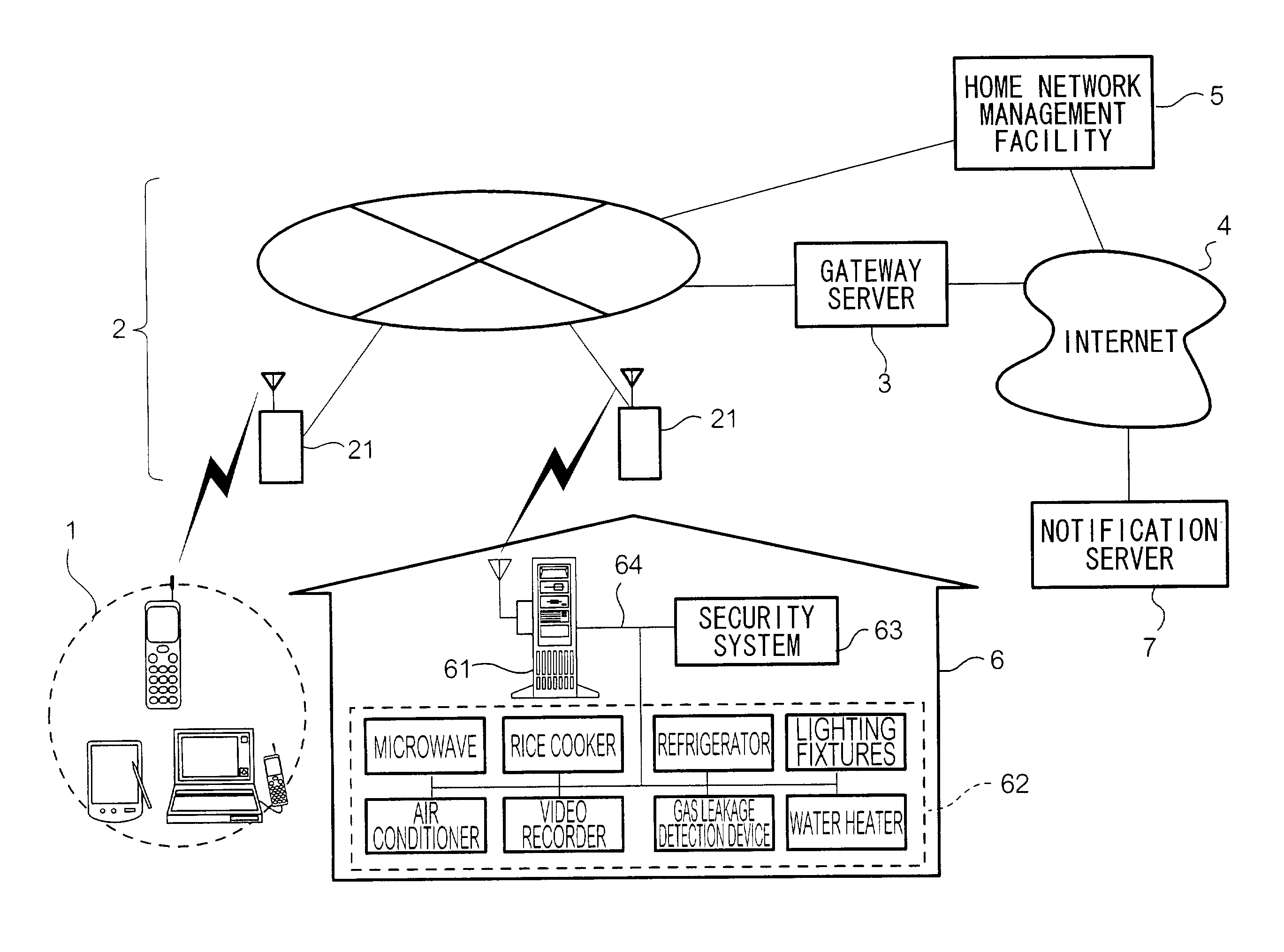
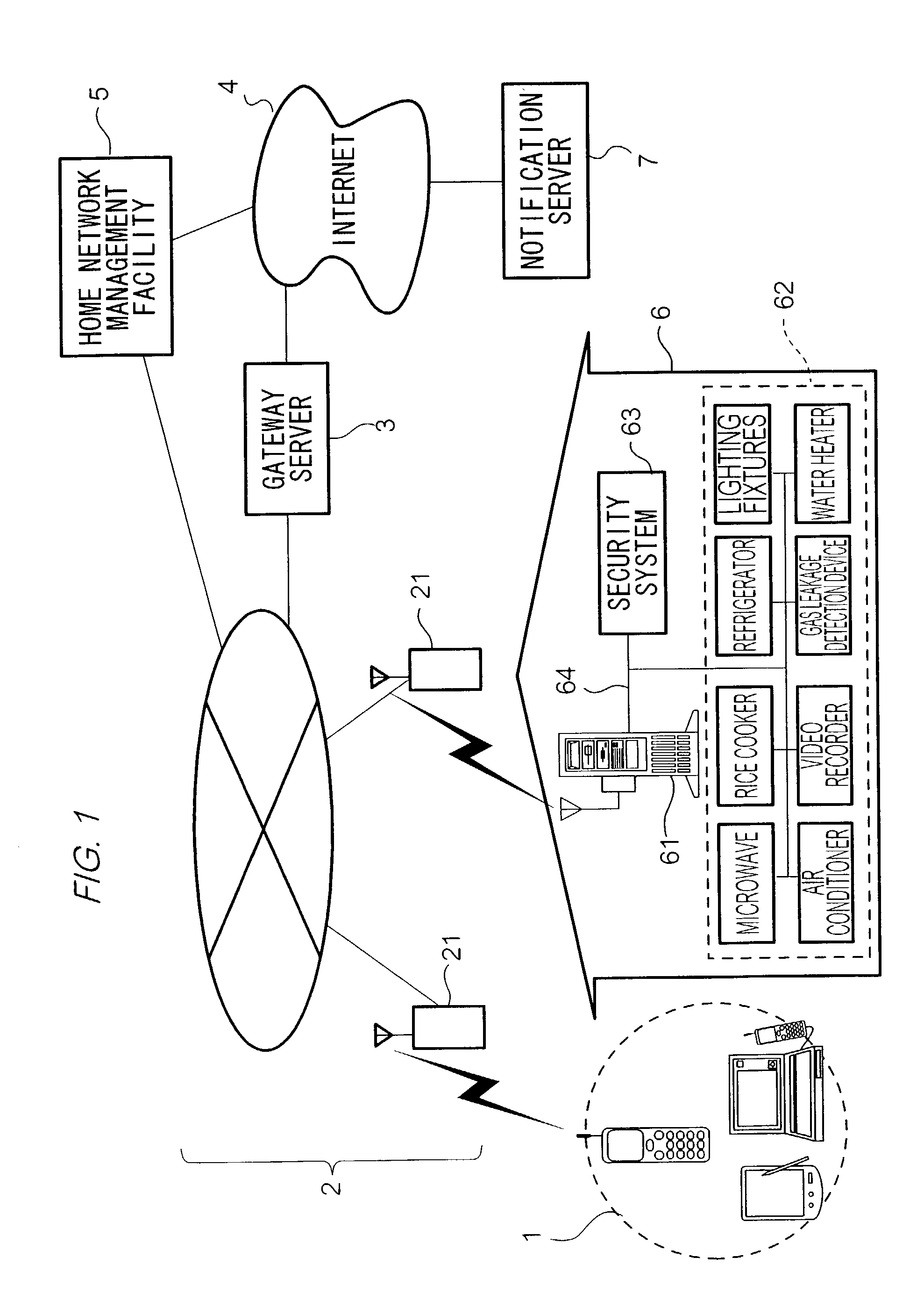
[0280] FIG. 25 is a block diagram illustrating the configuration of the remote control system in this embodiment. As shown in this figure, the same numerals are attached with regard to the same elements in the FIG. 1.

[0281] As shown in this figure, the remote control system comprises car network management unit 500, and car network 600.

[0282] Car network 600 is the network provided in a car; and comprises car server 601, key control unit 602, security system 603, engine control unit 604, GPS (Global Positioning System) 605, air conditioner 606, and bus 607 which connects these mutually.

[0283] Key control unit 602 authenticates a key being inserted into a key cylinder. The unit is connected to a starter of the engine, and detects whether the engine has been started. The way to authenticate the key being inserted into the key cylinder can be selected. For example, IC is provided in the key, and a body number ...


PUM


Abstract

A security system 63 and an electronic group 62 to be stored in a home network 6 are controlled by a home sever 61. A home network management facility 5 obtains status information showing the status of the electronic device group 62 from home server 61 when a user of electronic device group 62 operates a terminal 1 to make a request to home network management facility 5. Next, home network management facility 5 displays a screen for showing the status of electronic device group 62 on a display unit of terminal 1 based on the received status information, generates display information for displaying a screen for prompting input of a control instruction of the home-located electronic devices to the user on the display unit of terminal 1, and transmits the display information to terminal 1. And, home network management facility 5 performs remote control of electronic device group 62 based on the received control instruction via home server 61 when obtaining the control instruction from terminal 1.

Description

[0001] The present invention relates to a method for remote control of home-located electronic devices, and a management facility.ART BACKGROUND[0002] A variety of home-located electronic devices such as, televisions, video recorders, air conditioners, microwave ovens, washing machines, and personal computers (PCs) are currently being used in the home. While such devices are frequently used independently, due to the lack of a common user interface, they are rarely used in conjunction with each other.[0003] Obviously, if such devices could be controlled using a common user interface and also collectively managed, their ease and range of use could be greatly enhanced.[0004] There are known several different methods for controlling household home-located electronic devices. In one method, a home server is provided. This server is used to control a home network, which is used in turn to control household home-located electronic devices.[0005] By utilizing such a system, it has been prop...

Claims


Application Information

Patent Timeline
Patent Type & Authority Applications(United States)
IPC IPC(8): H04L12/28
CPCH04L12/2803H04L12/2805H04L12/2827H04L12/2814H04L12/2809
Inventor NAGAOKA, TATSUJINOMURA, KAZUOHIRUMA, YUTAKA
Owner VIVINT INC
Why Eureka
Try Eureka