Chip holding arrangement, pad printing system incorporating the arrangement, and method of pad pringting a chip using the arrangement

a technology of pad printing and arrangement, applied in the field of marking of chips or tokens, can solve the problems of increasing the effective surface area of sealed connection and vacuum holding force, not being very well suited, and increasing the cost of these plants

Inactive Publication Date: 2002-12-12
GAMING PARTNERS INTERNATIONAL CORPORATION +1
View PDF40 Cites 12 Cited by
  • Summary
  • Abstract
  • Description
  • Claims
  • Application Information

AI Technical Summary

Benefits of technology

[0014] The use of an elastomeric seal between the chip and the support limits the leakage (and the vacuum requirement). Furthermore, the peripheral placement of the seal very substantially increases the effective surface area of the sealed connection and of the vacuum holding force acting on the chip. Thus, when the chamber is isolated from the vacuum suction, it is possible to maintain an operational vacuum (capable of keeping the chip firmly on its support) for about one hour. The isolation between the chamber and the vacuum source makes it possible for the vacuum resource, especially the power and the flow rates of the vacuum pump, to be better controlled and used. Moreover, since it is possible to physically disconnect the holding device from the vacuum suction within the context of a high-rate multi-station pad-printing system, the vacuum circuits are very substantially simplified. In practice, it is possible to utilize only one or two stations for placing and removing chips, past which the holding devices move.
[0016] According to another variant of the invention, the annular seal is a washer with flat faces. The use of a washer with flat faces makes it possible, on the one hand, to provide good sealing with chips whose faces have a slight relief (for example chips with "granite-like" faces), and on the other hand, to already provide the chip with good seating for the pad-printing procedure of the chip faces.
[0018] According to yet another variant of the first version of the invention, the end face of the support comprises a stiff peripheral supporting ring arranged radially outside the annular seal and intended to act as a fixed bearing surface for the chip. The seal protrudes slightly in an axial direction outside the ring when at rest, in order to provide vacuum-tight sealing at the face of the chip. Thus, the peripheral supporting ring lying in a plane perpendicular to the axis of the support provides perfect seating and a constant axial position with respect to the pad-printing pad. This enables side pad-printing with very high accuracy, including sequential multicolor pad printing.
[0020] It should be noted that keeping an operational vacuum in the vacuum chamber for a fairly long period of time enables early retraction of the centering ring (the combination of retracting the centering ring with the descent of the pads having become superfluous) and also simplifies the mechanical devices used.
[0025] The invention also relates to a novel pad-printing system that uses more than one holding device. This arrangement makes it possible to work on objects with a substantially flat face which have to be securely held by vacuum suction, such as for example etching or printing system and the like.
[0029] This type of holding device is well suited for side pad-printing. This is because the peripheral supporting ring lying in a plane perpendicular to the axis of the support provides perfect seating and a constant axial position with respect to the pad-printing pad, which makes it possible to carry out the side pad-printing with very great accuracy, including in multicolor.

Problems solved by technology

Although this type of system is generally satisfactory, it is sometimes limited when holding chips under vacuum in the more tricky cases.
For example, it is not very well suited for:
In addition, the use of permanent vacuum suction in high-yield pad-printing systems capable of marking several chips simultaneously requires assemblies which are often complex in terms of suction lines and of powerful vacuum suction means increasing the costs of these plants.
Furthermore, the peripheral placement of the seal very substantially increases the effective surface area of the sealed connection and of the vacuum holding force acting on the chip.

Method used


Image

  • Chip holding arrangement, pad printing system incorporating the arrangement, and method of pad pringting a chip using the arrangement
  • Chip holding arrangement, pad printing system incorporating the arrangement, and method of pad pringting a chip using the arrangement
  • Chip holding arrangement, pad printing system incorporating the arrangement, and method of pad pringting a chip using the arrangement

Examples


Embodiment Construction

[0049] The particulars shown herein are by way of example and for purposes of illustrative discussion of the embodiments of the present invention only and are presented in the cause of providing what is believed to be the most useful and readily understood description of the principles and conceptual aspects of the present invention. In this regard, no attempt is made to show structural details of the present invention in more detail than is necessary for the fundamental understanding of the present invention, the description is taken with the drawings making apparent to those skilled in the art how the forms of the present invention may be embodied in practice.

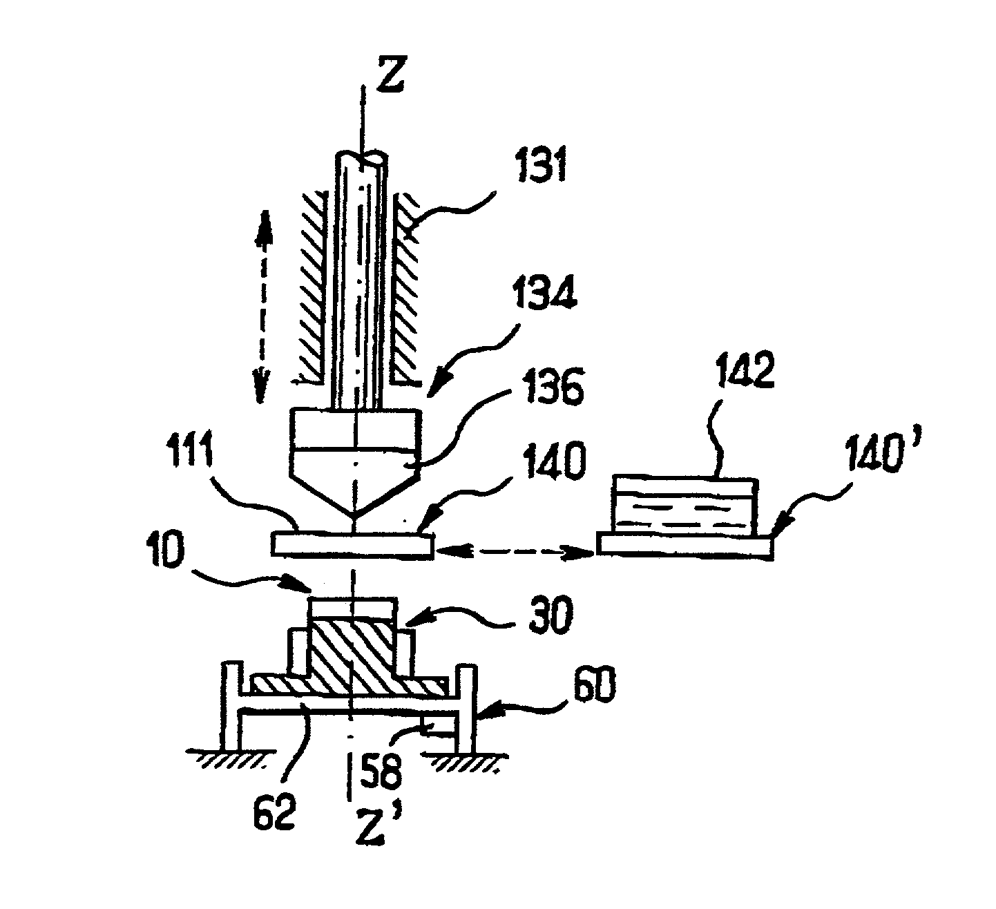
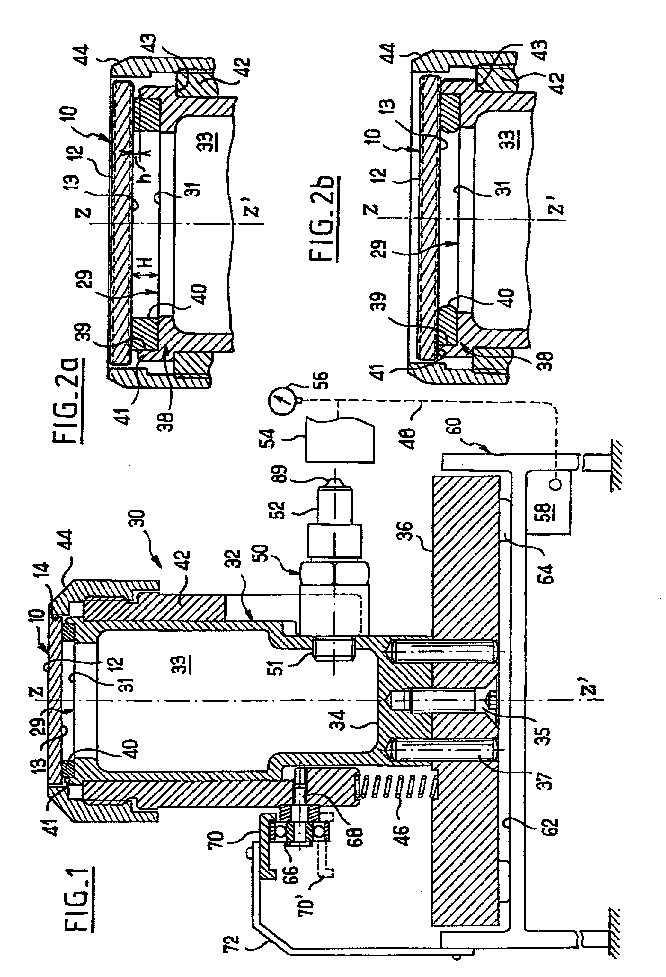
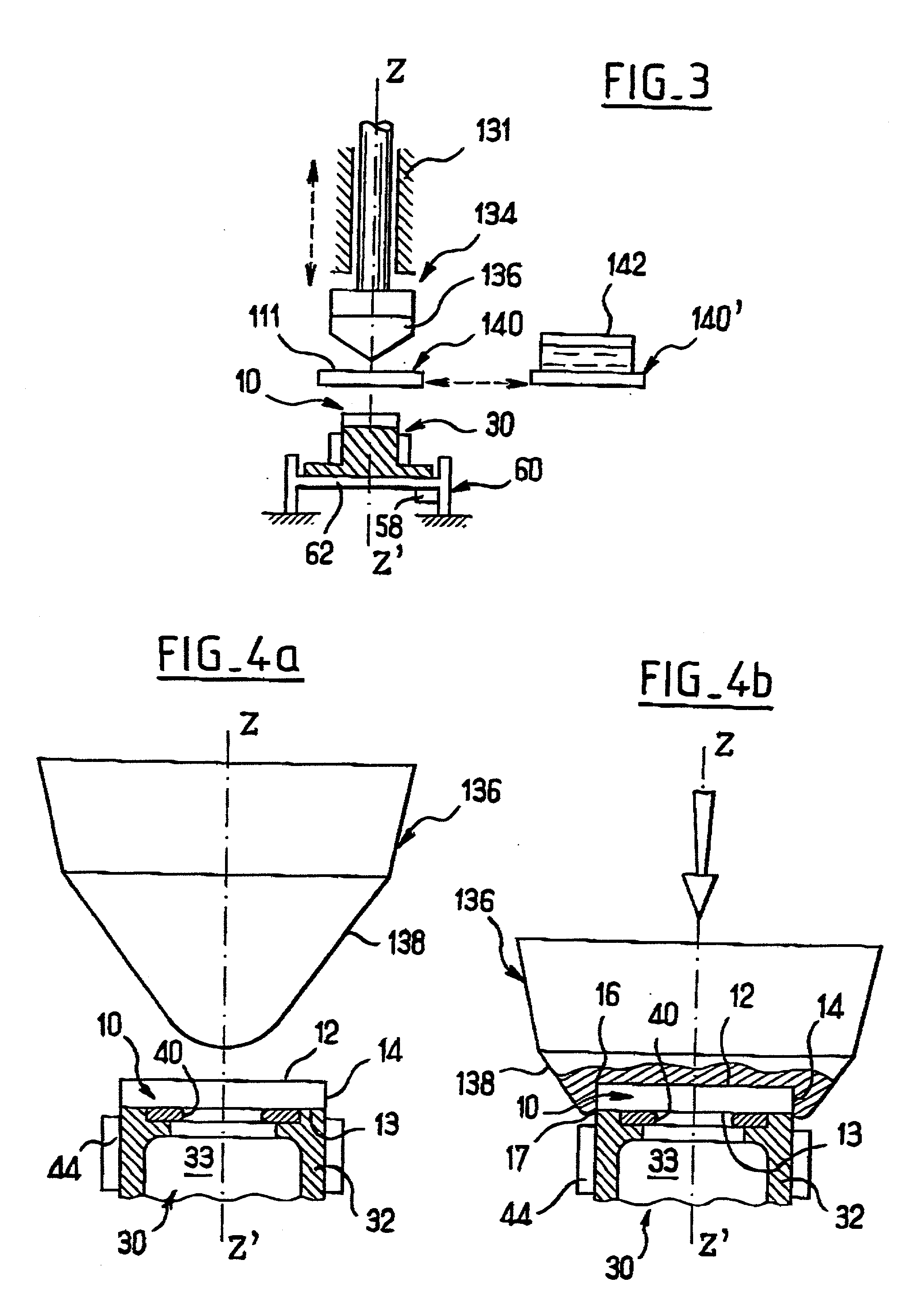
[0050] FIG. 1 represents a sectional view of a holding device 30 for a plastic chip or token 10 and designed, by way of non limiting example, to be incorporated in a pad-printing system or arrangement in order to mark, with an ink and / or varnish decoration, the faces and a perpendicular side of a disk-shaped chip 10. The chip...


PUM

PropertyMeasurementUnit
heightaaaaaaaaaa
heightaaaaaaaaaa
thicknessaaaaaaaaaa

Abstract

Holding arrangement for a chip which includes a support having a first end for supporting the chip. A vacuum chamber is arranged in the support. An annular seal is arranged at the first end. A vacuum source evacuates the chamber. A method of holding a chip in the holding arrangement includes placing the chip into the holding arrangement, pad printing the chip, and removing the chip from the holding arrangement.

Description

[0001] The present application claims priority under 35 U.S.C. .sctn.119 of French Application No. 01 07347, filed on Jun. 6, 2001, the disclosure of which is expressly incorporated by reference herein in its entirety.[0002] 1. Field of the Invention[0003] The present invention relates to the marking of chips or tokens for gaming tables having the general shape of a disk, or of objects of similar shape, by pad printing, and more particularly, the holding of chips or tokens during pad-printing operations. Gambling chips, also called casino chips, should be understood to mean any element which can be used in a gambling hall, especially on the gaming tables, and representing a nominal value which may or may not be predetermined. Generally, these chips are manufactured from a rigid and scratch-resistant plastic.[0004] 2. Discussion of Background Information[0005] Chips for a gaming table are, almost systematically, given a decoration by marking on their faces and / or sides. The decoratio...

Claims


Application Information

Patent Timeline
Patent Type & Authority Applications(United States)
IPC IPC(8): B41F15/20B41F17/00
CPCB41F15/20B41P2217/50B41F17/001
Inventor TOLLHUPP, MICHEL
Owner GAMING PARTNERS INTERNATIONAL CORPORATION
Why Eureka
Try Eureka