Method and apparatus for treatment of waste

a technology of waste treatment and waste, applied in the direction of lighting and heating equipment, solid fuel combustion, combustion types, etc., can solve the problems of troublesome waste, unfavorable environmental protection, and inability to treat all of these types of materials

Inactive Publication Date: 2002-12-26
APS IP HLDG
View PDF0 Cites 71 Cited by
  • Summary
  • Abstract
  • Description
  • Claims
  • Application Information

AI Technical Summary

Benefits of technology

[0019] It is an object of the present invention to provide a pyrolytic waste treatment system that his highly versatile, is efficient and reliable in operation and one that is easy to maintain.
[0022] Another object of the invention to provide a method and apparatus of the aforementioned character in which waste materials are efficiently and inexpensively converted into energy rich fuels such as combustible gases and fuel carbon and in which useful chemical by-products are recovered.
[0024] Another object of the invention is to provide a method and apparatus of the aforementioned character which will enhance the overall heat efficiency of degradation while precluding pollution of the environment.
[0033] It is still another object of the invention to provide an apparatus of the character described in which combustible gases generated within the reaction chamber are transferred to the thermal oxidizer and are mixed with air to produce a highly combustible gas which can be used to sustain the continued pyrolysis of the waste materials within the pyrolytic converter.
[0035] It is yet another object of the invention to provide an apparatus as described in the preceding paragraphs which is durable, efficient and highly reliable in operation.
[0036] Finally it is an object of the invention to provide an apparatus of the class described which is relatively inexpensive to manufacture, is simple to operate and one which can be operated on a substantially continuous basis with a minimum of problems and with little supervision.

Problems solved by technology

Waste is troublesome not only because it represents something that, as a general rule, cannot be used for any beneficial purpose, but also because it presents hazards to the environment in terms of the space it takes up and the deleterious effects it has on living organisms.
It has not been possible to treat all of these types of materials by ordinary combustion methods because offensive odors have been generated as a result of imperfect combustion, the production of components which are extremely corrosive, particularly at high temperature, adherence of fly-ash and the presence of substantial amounts of imperfectly combusted components in the residual ash.
Disposal of ash also poses problems such as the scattering of ash dust by means of winds or fouling of water.
Consequently, the difficulty in effecting complete combustion without harm to the environment has been such as to make the incineration operation uneconomical in many cases.
However, because of the very large volume of waste that is generated on a daily basis particularly in highly populated areas, acceptable landfill sites are rapidly reaching capacity and new sites have become difficult to find.
Many of these devices have proved unworkable or economically unfeasible.
Others, while feasible in concept have been proven to be inefficient and unreliable in continuous operation.
Still others, while attractive in theory, have been shown to be too expensive to manufacture, install and operate.
Several techniques have been employed to reduce the level of moisture in the waste before introducing it into the machine, because the presence of moisture makes the pyrolytic process less efficient.

Method used


Image

  • Method and apparatus for treatment of waste
  • Method and apparatus for treatment of waste
  • Method and apparatus for treatment of waste

Examples


Embodiment Construction

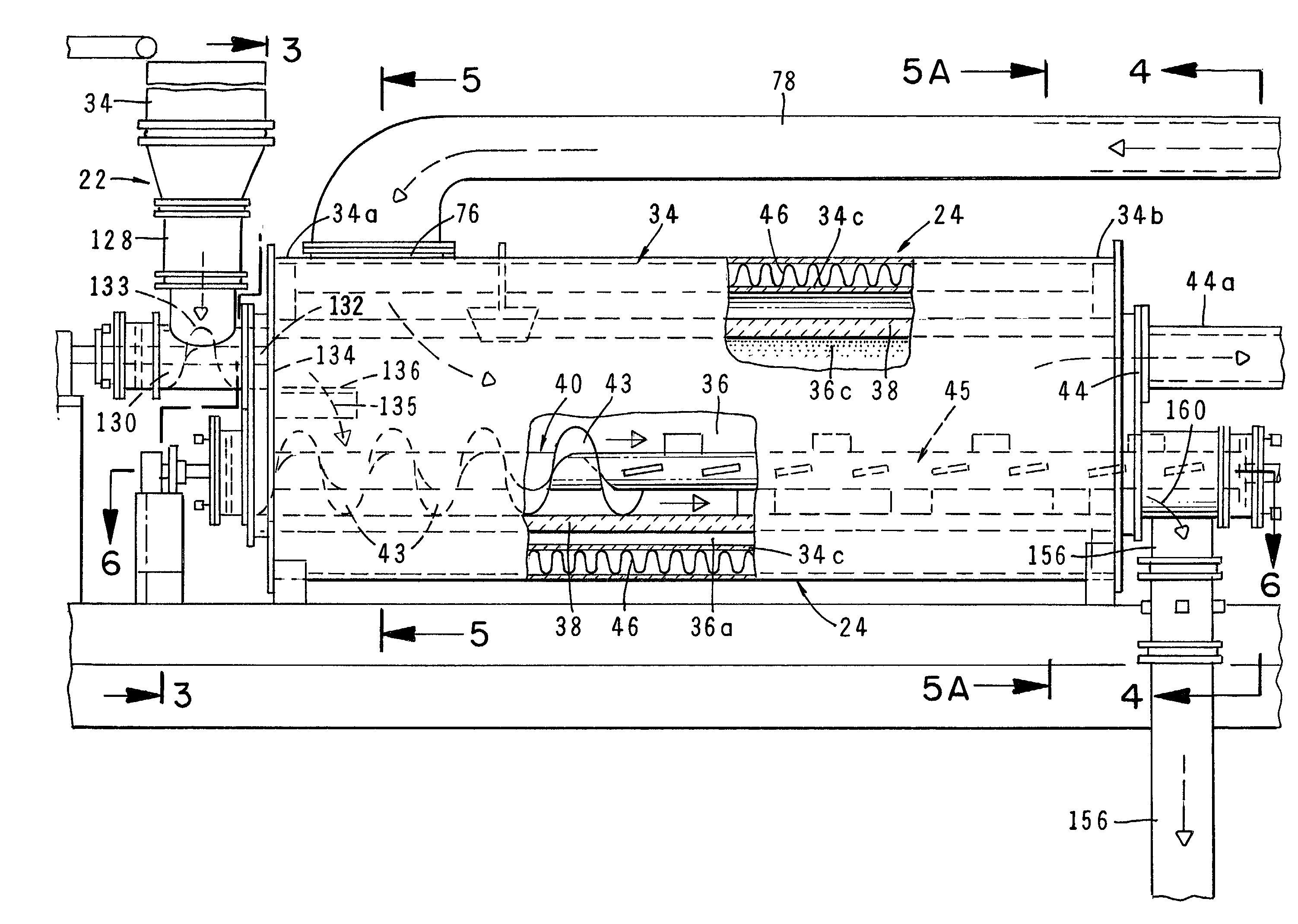
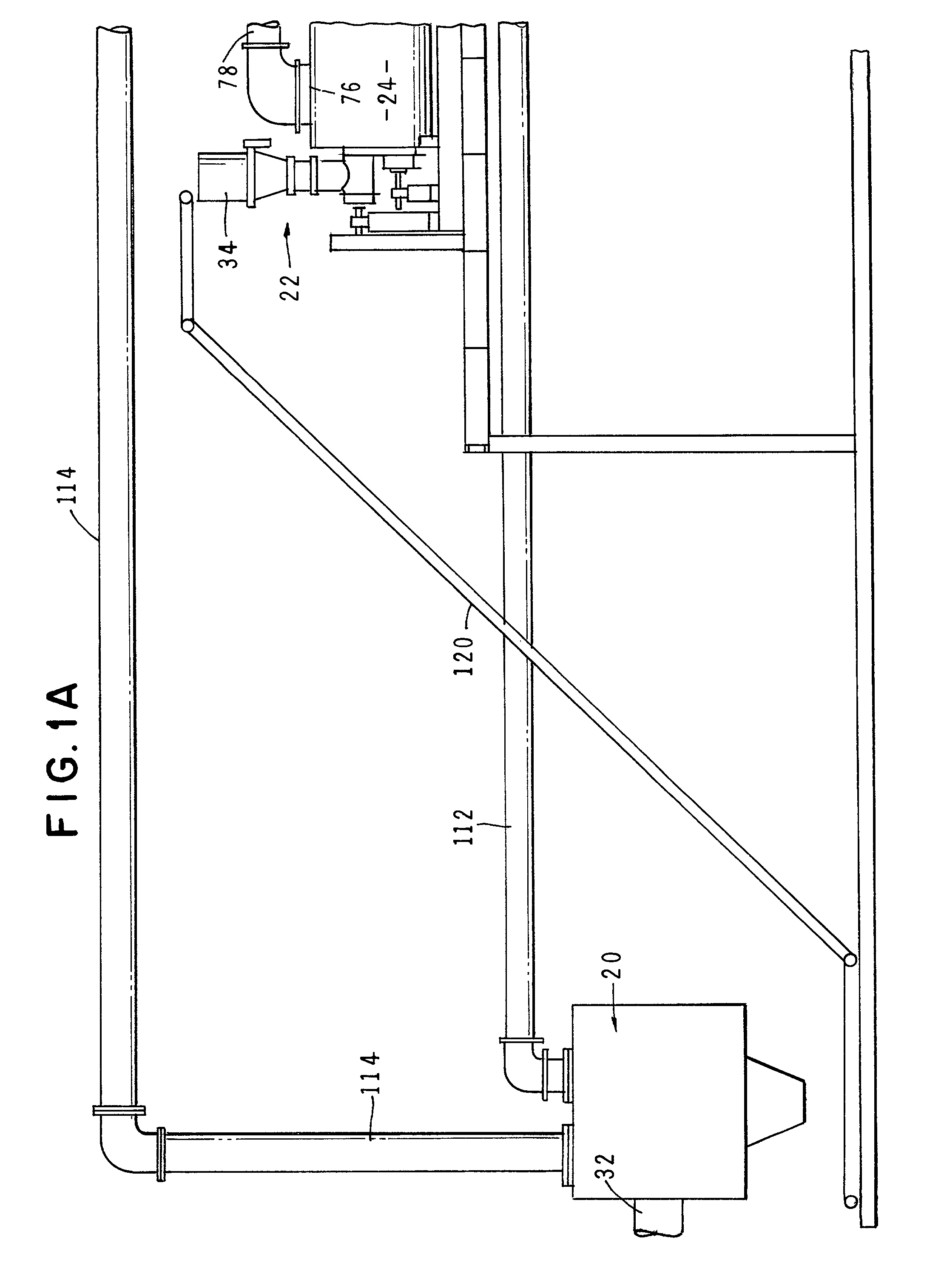
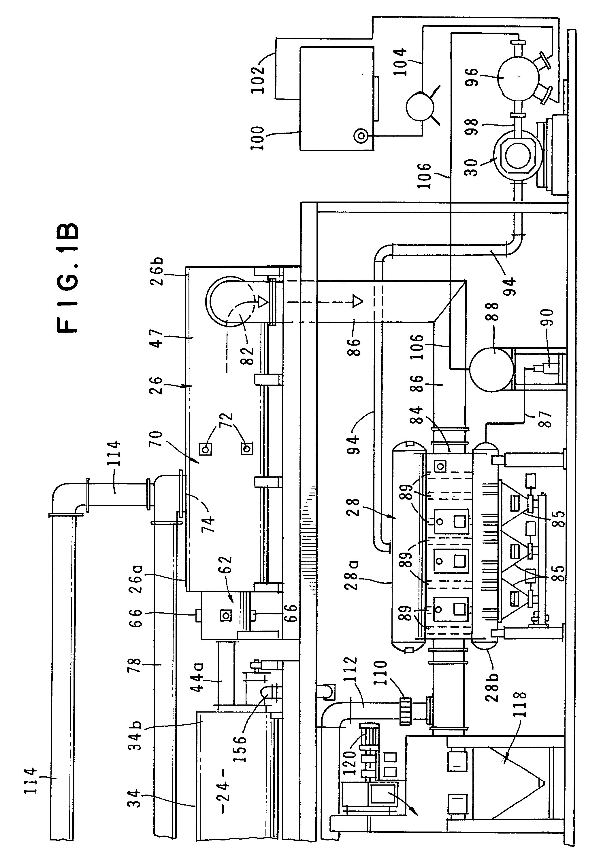
[0056] Referring to the drawings and particularly to FIGS. 1A and 1B, one form of the apparatus of the invention is there shown. The apparatus here comprises seven major cooperating subsystems, namely a dryer 20, a feed means 22, a thermal chemical reactor or pyrolytic converter 24, a two-stage, thermal oxidizer 26, a steam generator 28, and a steam turbine 30 that is driven by the steam converted by the steam generator.

[0057] In the operation of the apparatus of the invention, the waste material to be treated is first introduced into the dryer subsystem 20 via an inlet 32. After drying in a manner presently to be described, the dried waste material is controllably fed into the thermal reactor 24 by the novel feed means 22 which uniquely includes both a solid feed means and a liquid feed means. The solid feed means for feeding solid waste material to the converter comprises a gravity fed, bottom surge feed hopper 34 of the general construction shown in FIG. 1C. As will be described ...


PUM


Abstract

An apparatus for treating waste material that comprises four major cooperating subsystems, namely a pyrolytic converter, a two-stage thermal oxidizer, a steam generator and a steam turbine driven by steam generated by the steam generator. In operation, the pyrolytic converter is uniquely heated without any flame impinging on the reactor component and the waste material to be pyrolyzed is transported through the reaction chamber of the pyrolytic converter by a pair of longitudinally extending, side-by-side material transfer mechanisms. Each of the transfer mechanisms includes a first screw conveyor section made up of a plurality of helical flights for conveying the heavier waste and a second paddle conveyor section interconnected with the first section for conveying the partially pyrolyzed waste, the second section comprising a plurality of paddle flights. Once operating, the apparatus is substantially self-sustaining and requires a minimum use of outside energy sources for pyrolyzing the waste materials.

Description

[0001] 1. Field of the Invention[0002] The present invention relates generally to waste treatment systems. More particularly, the invention concerns waste treatment systems whereby the waste is processed by an apparatus comprising a thermal-chemical reaction chamber and a cooperating dual stage thermal oxidizer.[0003] 2. Discussion of the Prior Art[0004] Disposal of waste materials, such as trash and garbage has become a serious concern of industrialized nations. Waste is troublesome not only because it represents something that, as a general rule, cannot be used for any beneficial purpose, but also because it presents hazards to the environment in terms of the space it takes up and the deleterious effects it has on living organisms. For a considerable period, the disadvantages inherent in waste were largely ignored or, at least afforded little weight when a new process or new product that would produce waste was introduced, the benefits to society that the process or product would ...

Claims


Application Information

Patent Timeline
Patent Type & Authority Applications(United States)
IPC IPC(8): F23G5/027F23G5/44F23G5/46
CPCF23G5/027F23G5/444F23G5/446F23G2203/8013F23G2201/10F23G2201/303F23G2201/80F23G5/46
Inventor WALKER, WILLIAM C.
Owner APS IP HLDG
Why Eureka
Try Eureka