

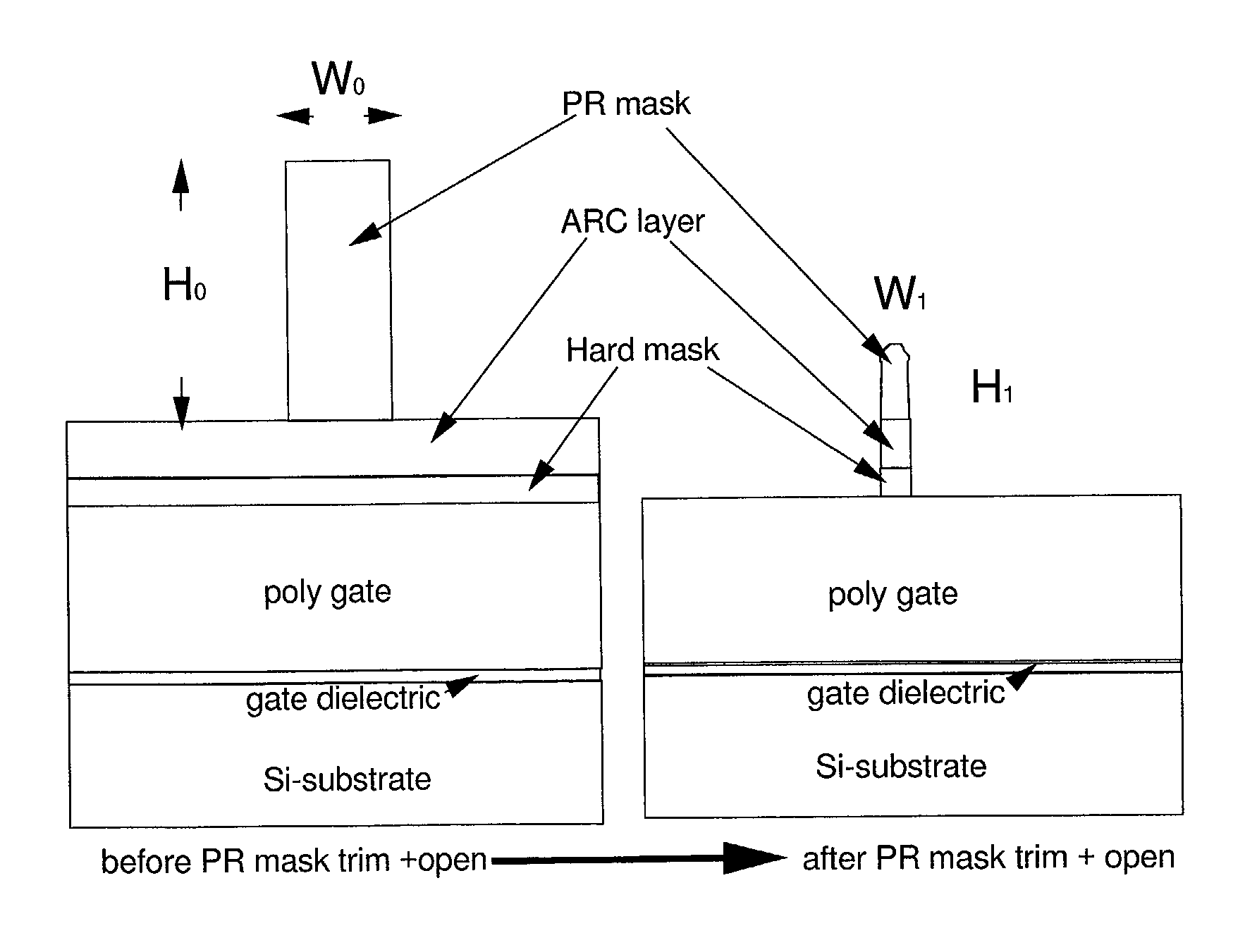
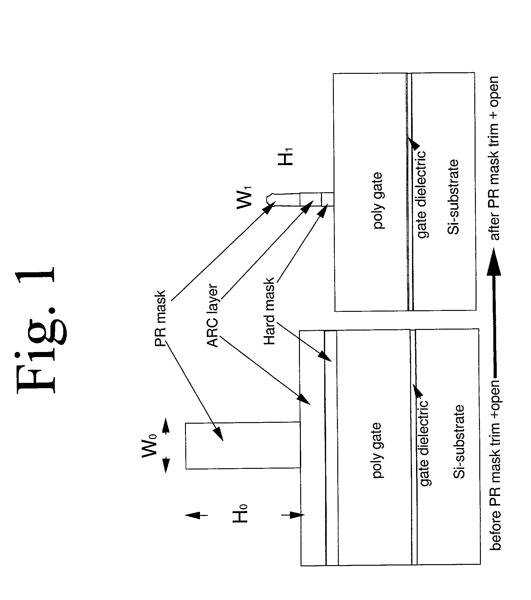
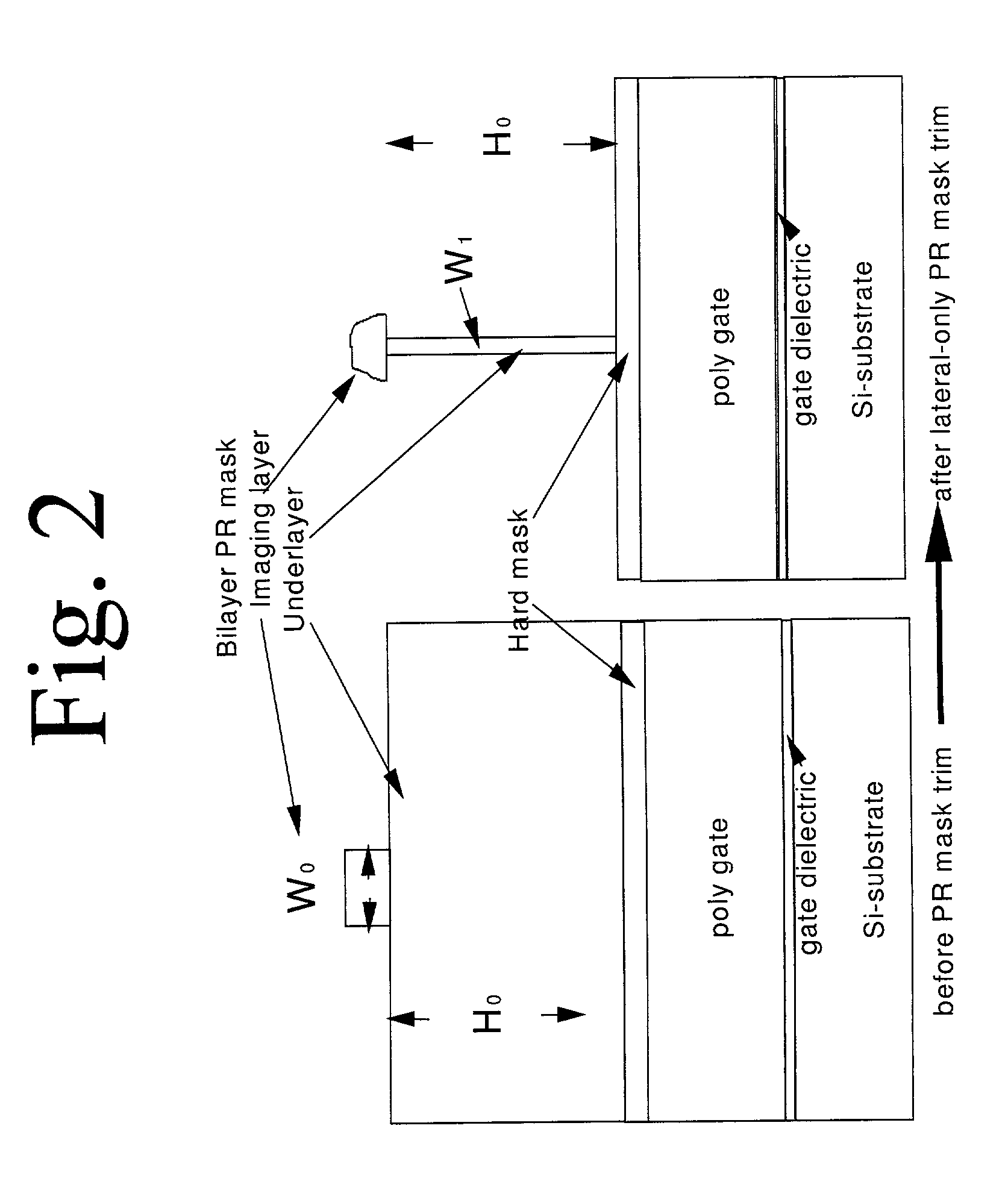
Lateral-only photoresist trimming for sub-80 nm gate stack
a gate stack and photoresist technology, applied in the direction of basic electric elements, electrical equipment, semiconductor devices, etc., can solve the problems of overlay correction capability, slow mass production, and hinder the wide use of x-ray lithography in the ic industry, so as to reduce critical dimensions
- Summary
- Abstract
- Description
- Claims
- Application Information
AI Technical Summary
Benefits of technology
Problems solved by technology
Method used
Image

Examples
Embodiment Construction
[0039] Reference is made to the figures to illustrate selected embodiments and preferred modes of carrying out the invention. It is to be understood that the invention is not hereby limited to those aspects depicted in the figures. As a matter of lexicographic convenience, the terms "underlayer," "organic underlayer," "anti-reflective coat," and "ARC" are used interchangeably.
[0040] The present invention relates to a process for generating a positive bilayer PR image, of reduced critical dimension, on a substrate comprising the steps of: (a) coating a substrate with an organic underlayer; (b) coating the organic underlayer with a top layer comprising a radiation-sensitive acid generator and a polymer having a silicon-containing, acid-cleavable group; (c) imagewise exposing the top layer to radiation; (d) developing the image in the top layer; (e) transferring the image through the organic underlayer down to the substrate; and (f) reducing the critical dimension of the transferred im...
PUM
 Abstract
Description
Claims
Application Information