Multi-lumen catheters and methods for using same

a multi-lumen catheter and catheter technology, applied in the field of multi-lumen catheters, can solve the problems of not being substantially oriented, not having high tensile strength, not being readily inflatable, etc., and achieves the effects of maintaining strength, precise lumen geometry and dimensions, and precise control of the size, shape and location of the lumens

Inactive Publication Date: 2003-02-06
CORTRAK MEDICAL
View PDF12 Cites 45 Cited by
  • Summary
  • Abstract
  • Description
  • Claims
  • Application Information

AI Technical Summary

Benefits of technology

[0013] Another object of this invention is to provide multi-lumen balloons wherein the individual lumens may be utilized, among other things, for drainage; for circulating heat transfer fluids; for housing electrical or guide wires or laser fibers; for accessing internal body locations with fluids, medicine, drugs, or medical instruments; and for facilitating passage of fluids, such as blood, around an obstruction including the balloon itself.
[0040] The foregoing method of preparing multi-lumen balloons in accordance with this invention is the preferred embodiment in most cases for producing perimetrical lumens forming ribbed protrusions from the exterior wall of the multi-lumen balloon. Such a design is useful where the multi-lumen balloon is to be inserted in a body lumen, and the main lumen formed by the inner balloon 40 is inflated such that inflation of the balloon 40 will have little or no effect on the pressure within the perimetric lumens 52, 54 and 56 protruding from the outer surface of the final multi-lumen balloon design because balloon 40 is substantially inelastic. This embodiment also illustrates that at least some of the lumens do not need to run the entire length of the balloon. This is also the preferred embodiment where relatively precise lumen geometry and dimensions are important. Selection of the mandrels or forming wires in this embodiment permits relatively precise control over the size, shape and location of the lumens and makes the results highly reproducible. This embodiment also facilitates producing lumens with somewhat different properties than the balloon. For example, for many applications it may be desirable to use a balloon 40 of high strength PET, but to choose a tube 60 made of thin-walled, heat-shrinkable polyethylene which would create polyethylene lumens and a very low friction outer shell for the multi-lumen balloon. The tubing 60 on the other hand can be made of biaxially oriented polyethylene terephthalate.
[0041] This embodiment of the invention also makes it possible to easily form a balloon having a perimetrical lumen 62 running, for example, in a helical pattern around the cylindrical wall of the balloon 64, as best shown in FIG. 6. Such a spiral perimetrical lumen can contain pinholes 66 along its length and can be used to precisely deliver medications or other fluids to select locations within the body cavity within which the balloon is placed, while at the same time independently providing balloon dilatation. Obviously, the geometric shape of such a lumen need not necessarily be helical, but can assume any conceivable shape for the particular application for which it is to be used.

Problems solved by technology

The relatively thick walls that define the lumens of conventional multi-lumen catheter shafts typically range from about 0.002-0.010 inches in wall thickness and, in any event, are not high tensile strength or readily inflatable under fluid pressure, nor are they readily collapsible under vacuum when operating at the pressures for which the device is designed.
The resulting shafts are typically not substantially oriented, therefore not high tensile strength.
Thus, the multi-lumen catheters of the prior art cannot, by themselves, function as balloons.
As a result the design of multi-lumen catheters which use balloons has been limited because these features provide design constraints.
While this procedure is often effective in relieving the symptoms caused by the disease by dilating the blood vessels for a substantial length of time, it will be evident that the balloon itself will occlude the blood vessel while it is inflated within the vessel.

Method used


Image

  • Multi-lumen catheters and methods for using same
  • Multi-lumen catheters and methods for using same
  • Multi-lumen catheters and methods for using same

Examples


Embodiment Construction

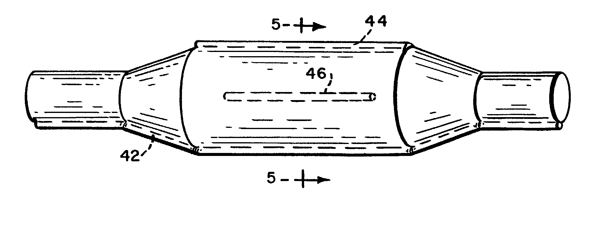
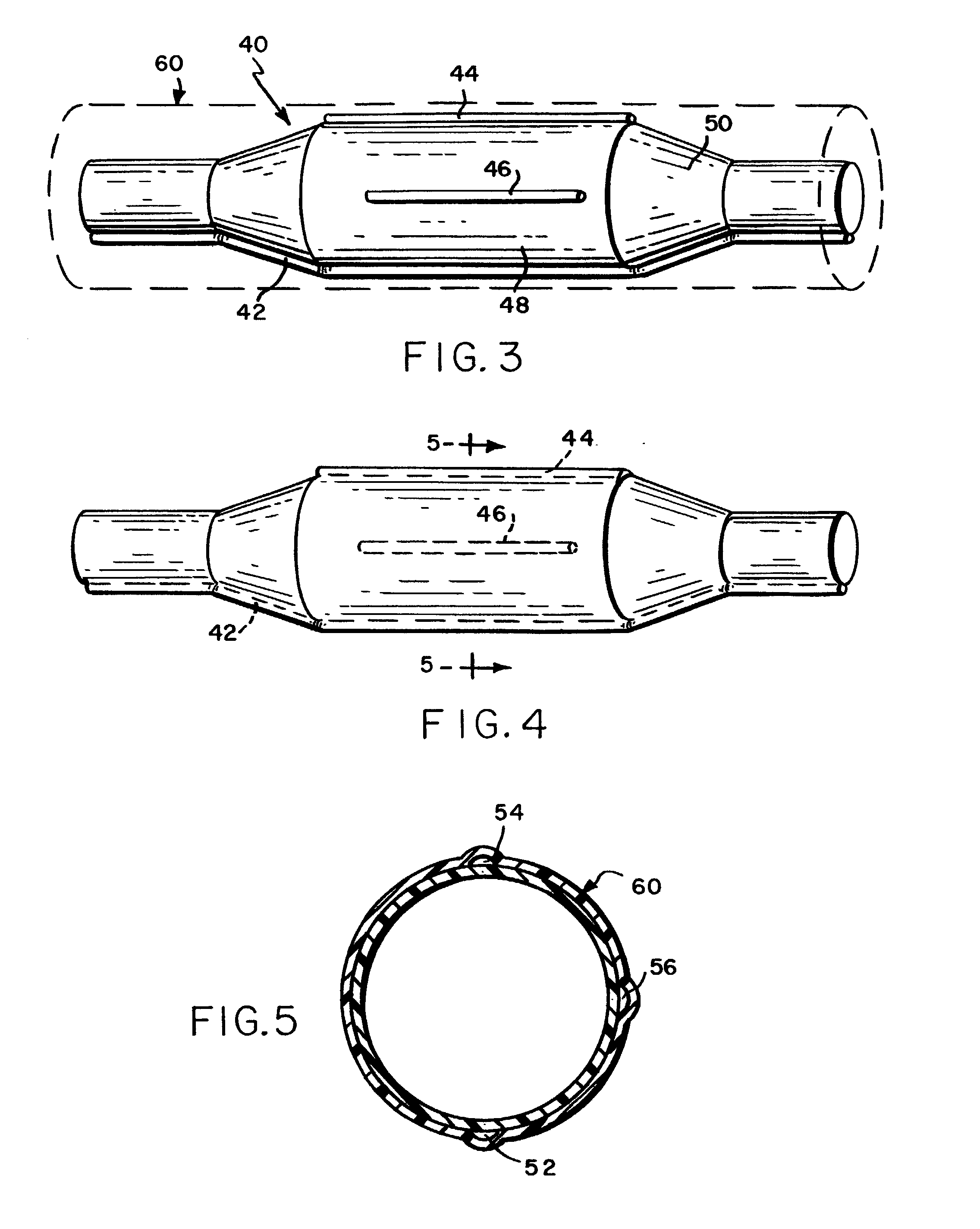
[0044] A 4 mm balloon with only one tapered end was fabricated from PET using conventional techniques. The balloon was placed over a mandrel for support and a wire rod (0.028" diameter) was laid up against the outside of the balloon. A piece of biaxially-oriented, thin walled, high strength polyester shrink tube was placed over the entire assembly and shrunk over the balloon and wire. The assembly was cooled and the wire and support mandrel removed resulting in a 4 mm balloon with an 0.028" "side lumen" on the outside of the balloon. In this case the placement of the wire end determined where the lumen ended along the balloon.

[0045] The multi-lumen balloon / catheter constructions of this invention can be used with virtually any catheter or balloon / catheter design including over the wire, fixed wire, rapid exchange, and other conventional as well as non-traditional catheter designs. In addition, the multi-lumen balloons of this invention facilitate the production of an entirely new an...


PUM


Abstract

Multi-lumen balloons for use as or in conjunction with balloon dilation catheters, and methods for making such balloons, are disclosed.

Description

[0001] The present invention relates generally to balloons and balloon catheters for internal body applications, and more particularly, to balloons having a plurality of lumens through which to access either the distal end of the catheter shaft or internal body locations, and to methods of making such multi-lumen balloons.[0002] The use and construction of balloon catheters is well known in the medical art, as described for example in U.S. Pat. No. 32,983 (Levy) and U.S. Pat. No. 4,820,349 (Saab). Balloon catheters are typically utilized as dilatation devices for dilating a blood vessel, e.g. a coronary artery, or other body cavity, although other uses have been developed, e.g., temporarily anchoring an instrument within a body lumen so that a surgical or therapeutic procedure can be performed. Other patents generally showing the application of various types of balloon catheters include U.S. Pat. No. 4,540,404 (Wolvek), U.S. Pat. No. 4,422,447 (Schiff), and U.S. Pat. No. 4,681,092 (...

Claims


Application Information

Patent Timeline
Patent Type & Authority Applications(United States)
IPC IPC(8): A61F2/958A61F7/00A61F7/12A61M25/00A61M29/02
CPCA61B2018/00166A61F7/123A61F2007/0054A61F2007/126A61M25/0009A61M25/0029A61M25/0032A61M25/1027A61M25/1029A61M25/104A61M29/02A61M2025/0025A61M2025/0031A61M2025/0034A61M2025/0036A61M2025/1031A61M2025/1072A61M2025/1075A61M2025/1086
Inventor SAAB, MARK A.
Owner CORTRAK MEDICAL
Why Eureka
Try Eureka