
Premix burner with high flame stability

a burner and flame stability technology, applied in the field of premix burners, can solve the problems of increased no.sub.x emissions, noxious emissions, absurd use of lean premix burners,

Inactive Publication Date: 2003-02-13
ALSTOM TECH LTD
View PDF9 Cites 22 Cited by
  • Summary
  • Abstract
  • Description
  • Claims
  • Application Information

AI Technical Summary

Benefits of technology

[0012] The net-like structure preferably should be designed so that it causes no negligible pressure loss or formation of local eddies that could substantially affect the flow in the mixing section.
[0018] It was shown that the thermoacoustic behavior of the burner can be positively changed with a net-like structure extending over the entire flow cross-section, and that as a result of this change a reduction of the oscillation tendency of the burner and therefore a stabilization of the flame are found. This positive effect apparently can be attributed to the nature of the net structure, i.e. the insulation and dampening of the sound waves propagating inside the combustion chamber.
[0021] This stabilizing effect of the net structure is additionally reinforced by the oxidation-promoting, catalytic action of its surface.

Problems solved by technology

However, a richer mixture would increase the noxious emissions and make the use of lean premix burners absurd.
It is also known that many times thermoacoustic oscillations occur in the combustion chambers of gas turbines, resulting in undesired effects, such as too high mechanical stress, increased NO.sub.x emissions due to inhomogeneous combustion, and even extinction of the flame.
Since, in order to achieve low NO.sub.x emissions, an increasing part of air is passed through the burners themselves, the sound-dampening effect of the cooling air flowing into the combustion chamber is reduced, so that the problems associated with undesired oscillations increasingly occur especially in such modern gas turbines.

Method used


Image

  • Premix burner with high flame stability
  • Premix burner with high flame stability
  • Premix burner with high flame stability

Examples


Embodiment Construction

[0007] The present invention is based on the objective of improving the stability of the lean premix combustion of modern burners of the initially mentioned type, as used in particular in the combustion chambers of gas turbines. In order to ensure operation with low noxious emissions, any significant increase in the combustion temperature must hereby be avoided.

[0008] According to the invention, this objective is realized with a premix burner of the type mentioned in Claim 1. The secondary claims represent advantageous embodiments of such a burner.

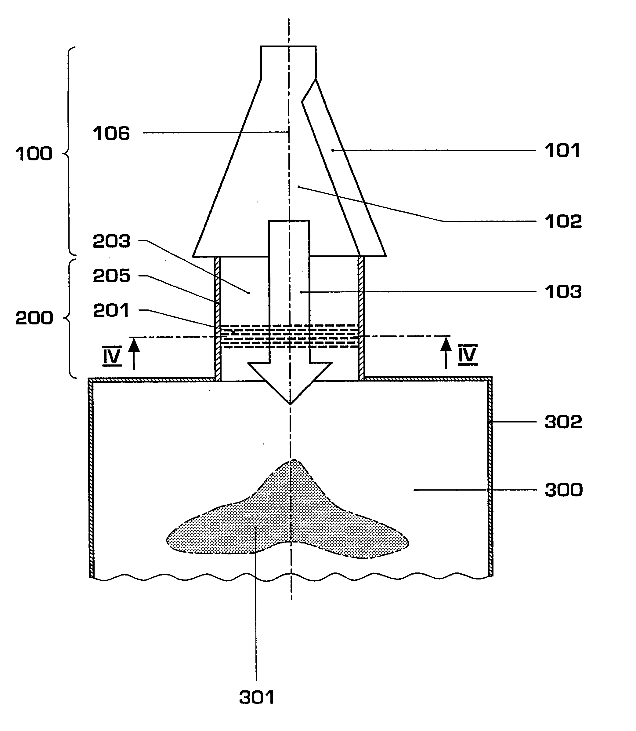
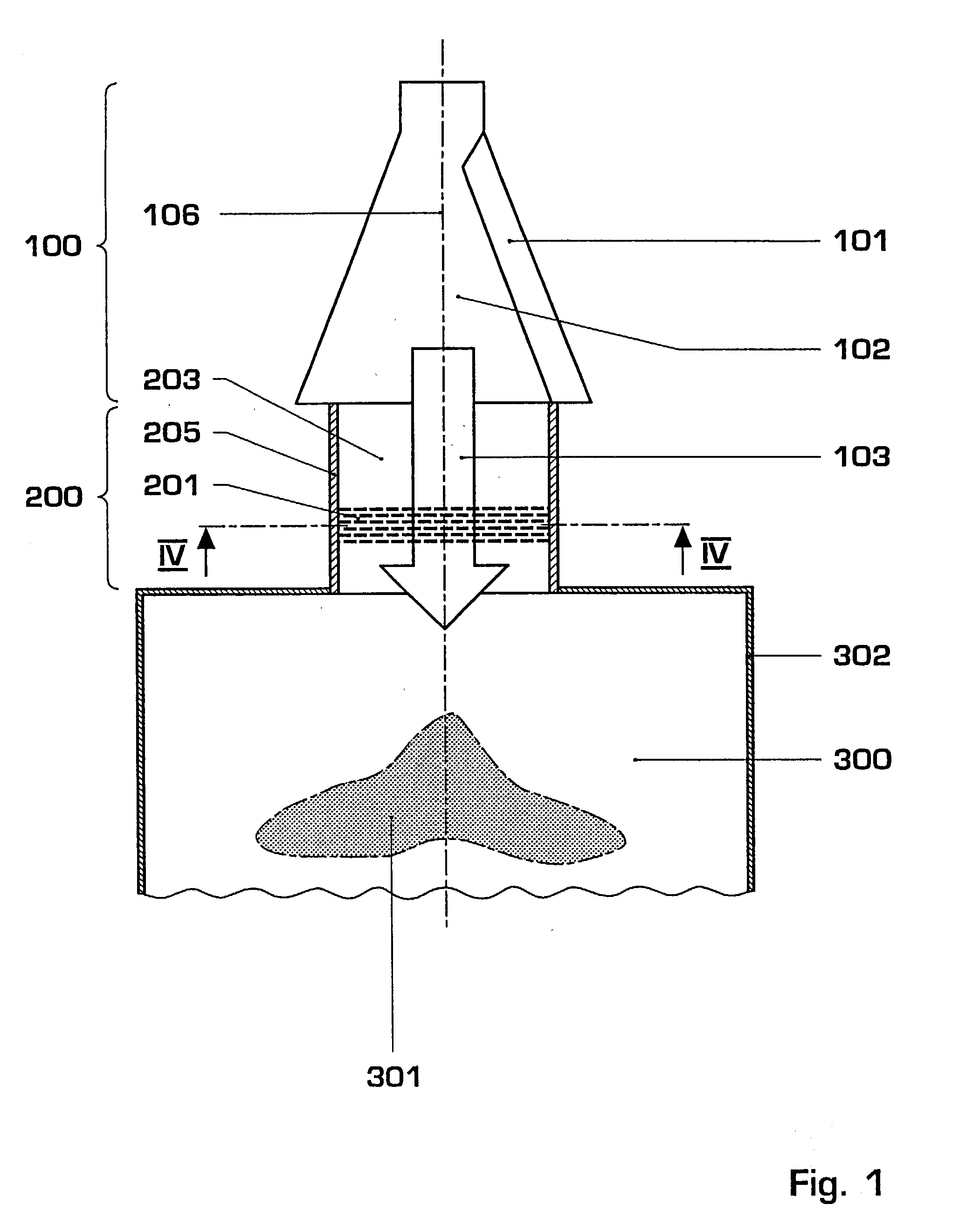
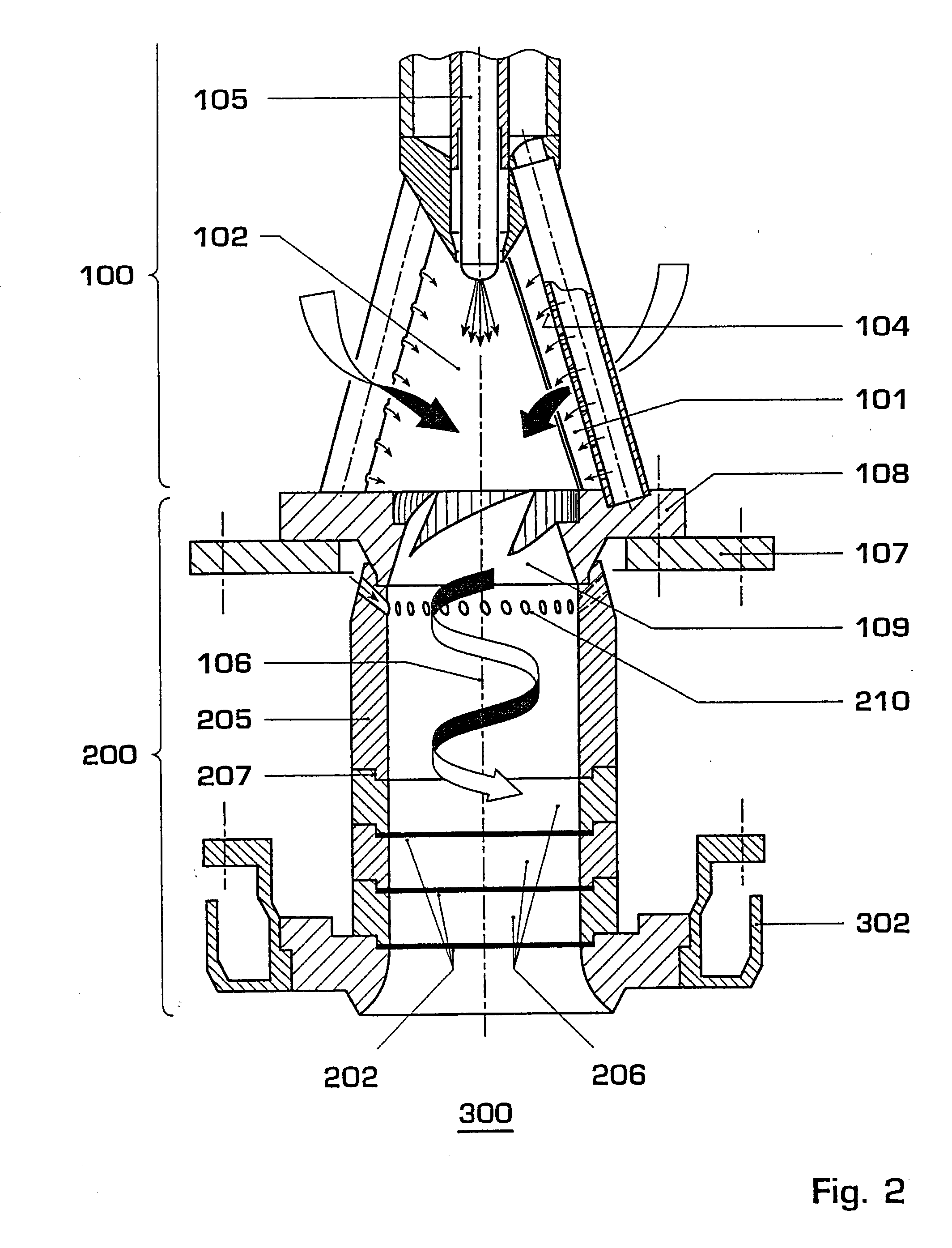
[0009] The basic idea of the invention consists of equipping a mixing section of a premix burner with a net-like structure that extends at least almost completely over the flow cross-section of the mixing section.

[0010] According to a preferred embodiment, the net-like structure consists of a wire mesh or a plurality of layers of wire mesh arranged at a distance from each other. An arrangement of five to 100, in particular ten to 20, wire ...


PUM


Abstract

The invention relates to a premix burner with high flame stability for use in a heat generator, preferably in the combustion chamber of a gas turbine. Modern, lean-operated premix burners enable very low noxious emissions, but sometimes operate very close to the extinction limit. To increase the stability of the lean premix combustion by increasing the distance between flame temperature and extinction limit temperature the invention proposes to equip the burner in the mixing zone (200) with a net-like structure (201) for the premixing of combustion air and fuel. According to a preferred embodiment, the net-like structure (201) consists of a plurality of layers of individual wire mesh fabrics (202) arranged at a distance from each other. The wire mesh fabrics (202) are preferably equipped with an oxidation-promoting, catalytically active surface. It was found that the net structure (201) positively influences the thermoacoustic behavior of the burner and dampens and insulates pressure waves from the combustion chamber (300), and in this way reduces the excitation of pressure waves in the combustion chamber (300).

Description

FIELD OF TECHNOLOGY[0001] The invention relates to a premix burner for a heat generator, in particular for use in a gas turbine system according to the preamble of Claim 1.STATE OF THE ART[0002] EP 0 321 809, WO 9317279, as well as EP 0 945 677 have disclosed premix burners in which a combustion air stream is fed via a swirl generator tangentially into an interior burner chamber and is mixed with fuel. Gaseous fuels, e.g. natural gas, are injected along tangential air inlet slits into the combustion air stream, whereas liquid fuels, such as heating oil, are injected preferably via a central nozzle at the burner head. At the burner outlet, the resulting eddy current bursts open at a change in the cross-section, inducing a backflow zone used for stabilizing the flame while the burner is being operated.[0003] In order to prevent interference with the flow field under the conditions of use in gas turbines, even if fuels of different origin and composition are used, and in this way alway...

Claims


Application Information

Patent Timeline
Patent Type & Authority Applications(United States)
IPC IPC(8): F23C7/00F23D11/40F23D14/74F23D17/00F23M20/00F23R3/12F23R3/28F23R3/36
CPCF23C7/002F23C2900/07002F23D11/402F23D14/74F23M20/005F23R3/12F23R3/286F23R3/36F23R2900/00014F23D17/002
Inventor GRIFFIN, TIMOTHYJANSOHN, PETERRUCK, THOMAS
Owner ALSTOM TECH LTD
Learn More